The following article comes from this link.
https://www.allpar.com/fix/fuel/vacuum-tank-fuel-pump.html
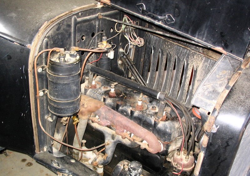
The vacuum tank is a fairly simple device using engine vacuum to pull gasoline out of the main tank and into a reservoir from which it gravity-feeds to the carburetor. The system, used and reliable until the late 1920s [and early 1930s], is important in an authentic restoration of an early vehicle.
The entire premise is dependent, primarily, on a leak-proof system. Even a slight leak - a tiny leak - will render the entire system useless. Repair is fairly simple, but requires a bit of patience. The following data is for the Stewart vacuum tank, but all systems are pretty much the same [in 1930, Chrysler moved to non-rebuildable tanks, but some cars might have continued to use this type]. Before disassembling the system, a couple of photos will be a reminder when you go to reassemble all of the pieces.
Essentially there are only three categories which would cause vacuum tank failure: lack of vacuum, bad internal valves, or a leaking vacuum system. Remove the vacuum line from the vacuum tank (the other end will be connected to the intake manifold). With the engine running, place a finger over the end of the line; if a slight ‘sucking’ is felt, it’s more than likely not lack of vacuum. Assuming that there is gasoline in the main tank and that there is no blockage (remove the gas tank cap and have a helper listen for ‘bubbling’ as you blow air back through the fuel line) the vacuum tank will have to be removed and serviced.
To rebuild or service the vacuum tank, first remove the entire system from the car. This will consist of an inlet line (from the main gas tank), a vacuum line (generally from a manifold connection) and the outlet line (easiest way is to disconnect from the carburetor). Then, of course, remove the mounting bolts holding the tank to the engine or firewall.
There is only one major caution for you: the top cover of the tank is generally made of pot-metal and, if not already cracked or broken, could easily break if too much pressure is exerted in removing or replacing a fitting. GENTLY, please!
Always use two wrenches when removing lines; one for the rotating fitting and the other for the ‘fixed’ or rigid fitting. As you remove a line, mark it with a piece of masking tape for later identification. Remove the vacuum line (from the tank top cover) the inlet line (from the top cover) and the outlet line, which may also include a shut-off valve, a filter assembly or a drain (from the very bottom of the tank).
Check all lines and fittings very carefully; a leak or bad threads on a fitting will result in air leakage and will prevent vacuum from building up. If that’s the case, replace the line with new copper line and fresh fittings. The fuel inlet line (again, there may be a filter between the inlet line and the tank itself) goes into the tank through the large fitting. When you remove the line fitting, there should be a filter screen in the inlet recess. Replacement fuel screens are available through a restoration supply house. Be sure the screen is perfectly clean.
The vacuum line attaches to the tank at a fitting often marked ‘vacuum’ - remove it. There will be a short, curved tube coming out of the top of the tank. It is a breather or vent tube. It may rotate in its fitting. That’s okay. Finally, there may be a small plug in the top (some tanks have one, others not); it’s a primer plug. Don’t force it to get it out. If it’s too stubborn, leave it alone. Remove the eight screws holding the top cover in place. And lift off the cover (it may be stuck - try a very thin razor blade to cut through the gasket and sealer that was probably used on it.)
Set the cover aside, along with the float attached to it, and remove the inner tank (often, another gasket and it too is probably stuck) and examine both tanks for rust. All rust has to be thoroughly removed, pinholes patched (soldering is often effective), and if badly pitted and corroded, treated with a gas-tank sealer. There is only one moving part on the inner tank.
Near the bottom is a ‘flapper valve’. It just hangs there. When there is vacuum in the system the valve is sucked tightly shut. Otherwise it is free to flop open and let gas flow into the outer tank. Make sure that it shuts firmly and that it’s not rusted or bent.
Now check the top and float assembly, there are two springs which activate the vacuum valve as the float is raised. Check that all three openings in the top are clear, and that the inlet screen is clean. Be sure that neither the small vacuum shaft (that goes into the vacuum outlet hole) nor the breather shaft are binding. Be sure that the entire mechanism operates freely as the float is raised or lowered. Check the float to be sure that it is not leaking, and be sure that the guide shaft on the bottom of the float is straight. Check the top of the outer tank and the lip of the inner tank to be sure that they are not bent or distorted; check the top assembly carefully for cracks (often tiny cracks can be repaired with JB Weld) and clean the mating surface.
That’s about it. Use new gaskets. Olson’s Gaskets has the proper size cork gaskets, with all of the holes punched. Some inner tanks have a lip with nine holes around the circumference; others do not and have only a tiny lip. If it is the first type, I recommend two gaskets - one between the outer tank and the inner tank, and a second under the tank top. The small-lipped inner tank requires only one gasket.
Be sure that the ‘extra’ (ninth) hole in the gasket fits over the breather tube protruding up from the tank, and that the hole under the breather tube in the top fits directly over it. If all of the other eight holes do not line align perfectly, you’ve installed the gasket incorrectly. Install the eight fillister head screws loosely, and then tighten in a pattern moving from one screw to the opposite side to put equal pressure on the top as it is snugged down.
Reinstall the tank and connect the outlet line to the carburetor. Attach the vacuum line to both the tank top and the manifold, and install the primer plug if it was removed. Prime the vacuum tank with no more than eight ounces of gasoline. (You may have to also fill the carburetor float bowl depending on the type of carb). Finally connect the fuel inlet line, check all lines for tight connections and once again, check the top screws for tightness. Make sure that there is fuel in the main gas tank, fire it up and the vacuum tank will keep a supply of gas going to the carburetor.