Introduction and what I did with my 'T'

Hello all. I’m a new member to this site and happily found it while internet searching for Model ‘T’ stuff. As this is a spot to tell what you did with your T today, I would like to share what I’ve done. I have recently taken over the responsibility of caring for my Dad’s '26 Tudor that we restored and put back on the road about 12 years ago. It is getting some needed love. This past 2 weeks, rear axle removed, pumkin split and re-sealed,(dripped ever since rebuild 8 yrs ago…grrr) dis-assembled spring pack, cleaned and graphite lubed the leaves, assembled and re-installed along with replacing the original spring bushings and shackles. Today, front axle was dropped in preparation to re-bush springs and perches. Also going to do to the spring pack as what was done to the rear. This is just a start as to what I want to do for this car over the winter. I’ve had the fun and the pleasure of restoring this car with my Dad (still here but unable), and now the honour of continuing the stewardship of preserving a piece of history. Thank you for letting me introduce myself and sharing.

Mark in Canada.

2 Likes

Welcome aboard!
I’m in the process of putting my dad’s '24 Fordor back on the road, so I’ll look forward to reading about your adventures.

Thanks, appreciate the comments. Hope to post a picture of it soon.

I wonder if you looked at the rear axle shims while it was apart? I hope they were bronze.

You should look at the bushing at the base of the steering column where the frame bracket attaches. They are always shot.

My Dad and I rebuilt the rear end about 8 years ago. Ring and pinion failed. Someone else had been in to to because it was bronze but didn’t do a good job with the re-assembly and it imploded. We put in new ring and pinion gears along with modern thrust bearings, axle bearings and seals at that time so as to not have to worry about another failure. I’ll have some pictures tomorrow of the front axle shackle re-bush.

Saw a mistake in my above post, can’t change it, got two “to’s” in a row…lol. On to better stuff…of what I did with my ‘T’ today. Made a couple of pieces to install the spring perch bushings. The piece on the left I made to do the rear spring bushings, and is the same size for the front. The piece on the right had to be made as the perch (as you all know) is smaller, therefore a smaller sleeve had to be made to allow the old bushing to be pushed out.

Sorry, I didn’t realize that my pictures weren’t very clear until I came to post them. The next shot is as I’m pushing the old bushing out using 3/8 threaded rod as the mover.

This is after it’s out on the floor, mandrel, bushing and collar.

And now the install. As I pushed it in, I dribbled a little retaining compound on the outside of the bushing as it was going in really easy and wanted to make sure it wouldn’t move.

Spring pack has been re-assembled and painted to dry over night for install tomorrow.

1 Like

That is how I do it but I use deep sockets and a hydraulic press. I put lots of grease on the new bushings to make it easier. They can’t escape once they are installed.

You’re correct, they can’t escape. My concern was that they might rotate in the perch and the oil hole not line up and not be able to lubricate them at some point. Might take a while though considering that I changed out the original bushings. :laughing:

Here’s something else that I’ve been working on. The mag on my car blew up on my Dad a few years ago. Glad it was just idling in the driveway and he wasn’t going down the road. Broke the hogs head as you can see below. I’m sure that I’m not the only one to experience this. So I thought that it would be a perfect candidate to make my own outside oil line for the front. As you can see the square hole near the top, but first have to fix the breakout.
(edit: sorry, some of the pictures are sideways)

First, make a patch, drill and tap the hogs head. Drilled and tapped for the oiler at the same time.

Installed the patch with 6-32 machine screws and a red thread locker and some gasket material out of a tube( not silicone) made by the same company that made the thread locker.

Then the piece to catch the oil. I didn’t make a scoop for the inside, but incorporated an area to catch the oil and so it will collect inside the adapter and allow it to run out the tube. That’s the area on the plate below the square hole.

This is the inside view of the top part of the oiler. Cut a piece of 1” stainless tube on angle as close to the shape of the hogs head as I could. Machined a piece of stainless bar to fit inside, drilled and tapped for ¼” npt and welded it in the end of the tube.

Then welded it to the plate and mounted it with the same gasket material.

And for the final touch for the break. Filled the hole with metal infused epoxy sand it down and paint. It’s now ready for install when I get to that part of my winter T chores.

1 Like

Like! Well done. That should work.

Thank You! I hope so. It will be better than the one that is on the car now which the oil has to travel vertical out of the hogs head before it can dribble down the tube.

Hope everyone had a good Christmas and a Happy New Year to all. It’s been a busy time lately. My car has a water pump and it needed re-packing. I found out when I removed it, that it need a bit more. The set screw for the pulley had loosened and spun on the shaft damaging the end. The pulley hub had worn and now did not fit the shaft properly. So, I made a new shaft and instead of a divot for a set screw, milled a 1/8" keyway.

Then, to address the pulley. Needed to remove the three rivets that hold it together.

Chucked it in the lathe and peeled of the top as close to the pulley as possible without scoring the side, and knocked them out with a punch.

Then to machine a new hub. Apologies that these pictures did not come clear. They looked good on the camera screen.

And then part it off.

Drilled out the centre and machined to fit the shaft, and broach the keyway in the bore. You will see two keyways, unfortunately the broach took off on an angle and cut too deep on one side of the bore making it unusable, so a second keyway had to be broached. Drilled and tapped the 3 holes for 8-32 machine screws and assembled. My apologies again, I forgot to take a picture of the finished pulley.

Then had to address the fan as it has a bit of a wobble. Found that the bushings were loose, so I machined two new ones and pressed them in. The white ring is a nylon washer that I made to take out some of the end play that was there before.

When I got the hogs head off, I noticed a shiny ring around the middle of the low drum. Nice easy access, pulled out the bands and low was done with some of the rivets rubbing the drum.
My Dad, quite some time ago, bought some Kevlar bands, so they got installed.

And then the original hogs head (repaired) with the added external oiler re-installed back on the car.

And the to-do list gets a bit shorter

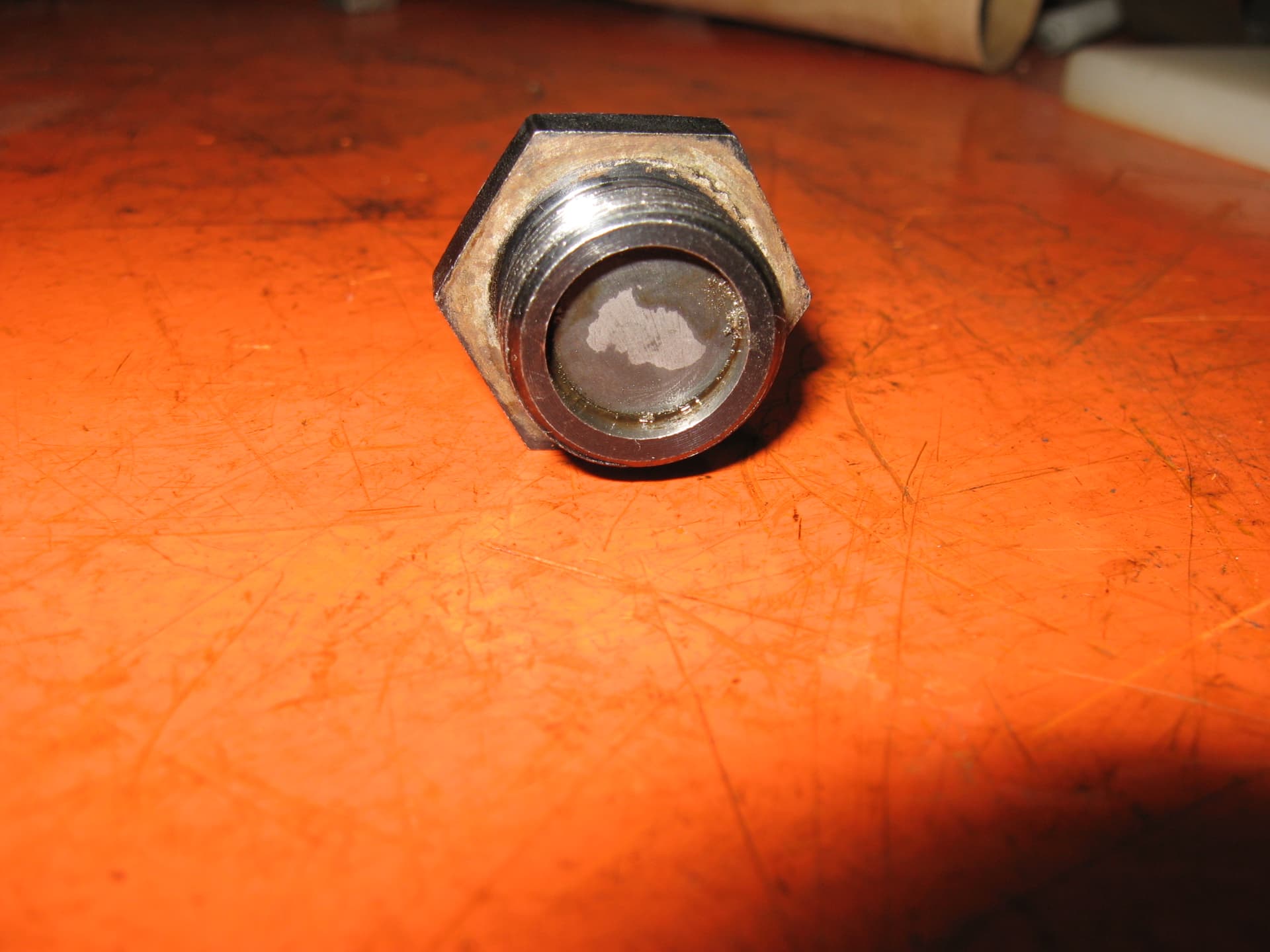
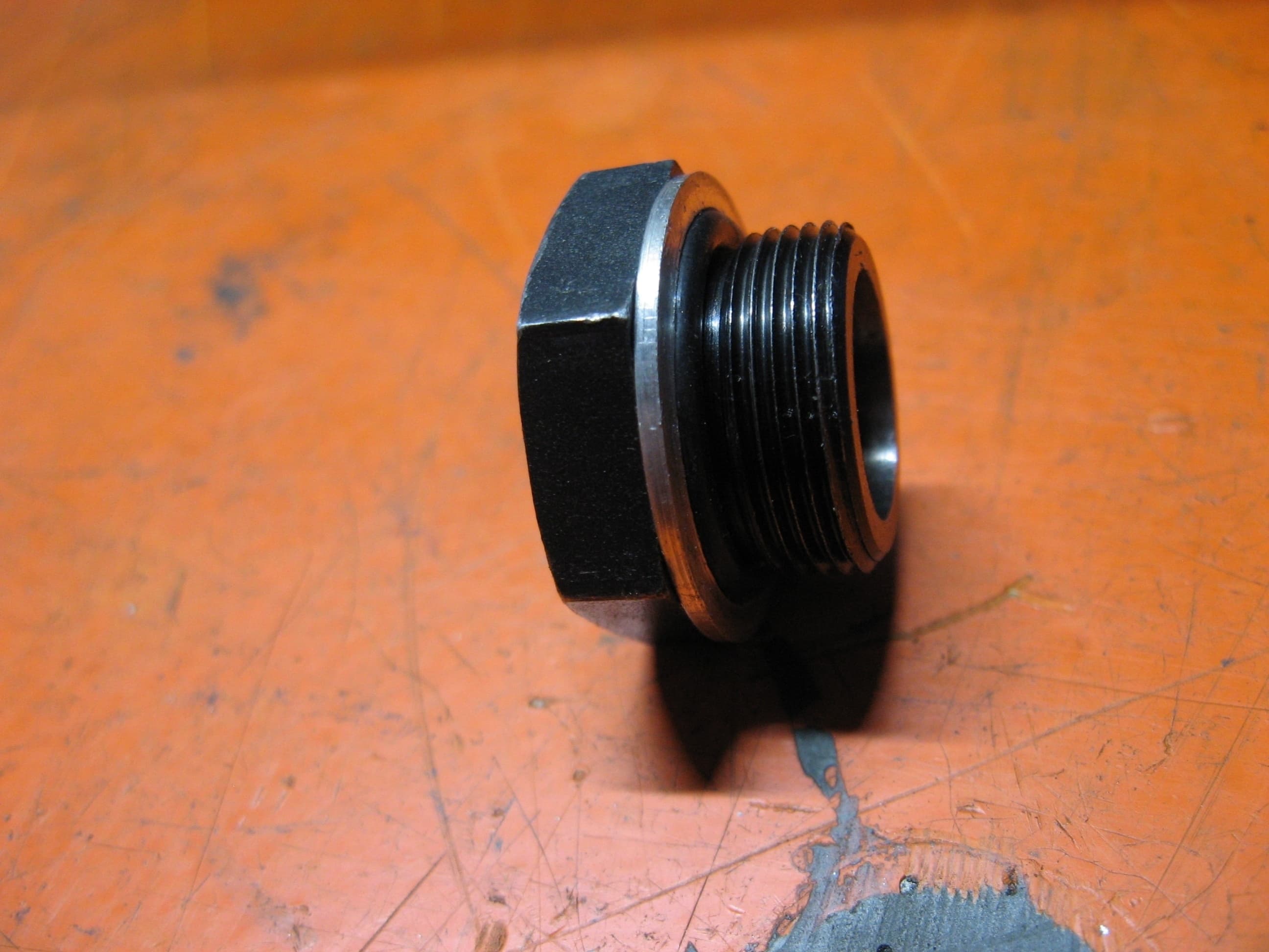
Hello all. I’ve have been working on my winter to-do list. I have a few more things to share. I’m not sure what happened to the sealing ring that is supposed to be on the oil pan plug, so I thought I’d try something to remedy the situation. Here’s a picture of the aftermarket magnetic plug.

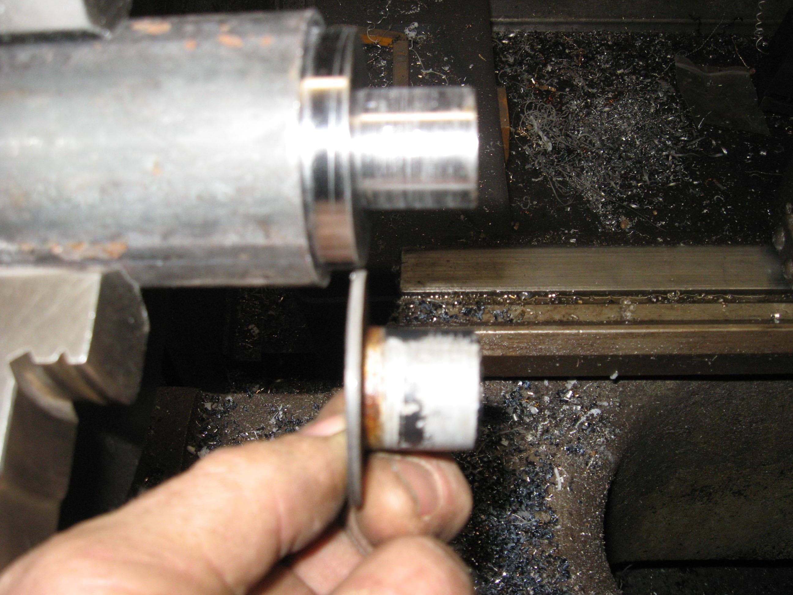
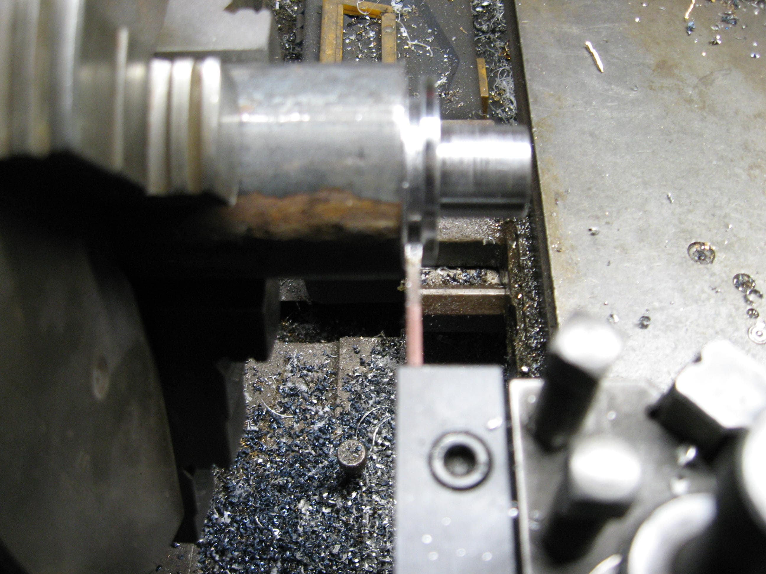
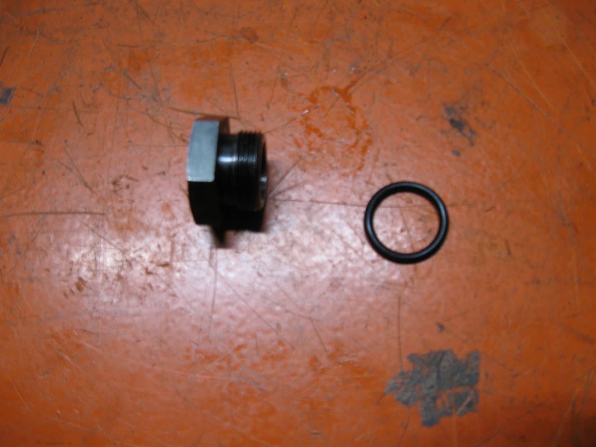
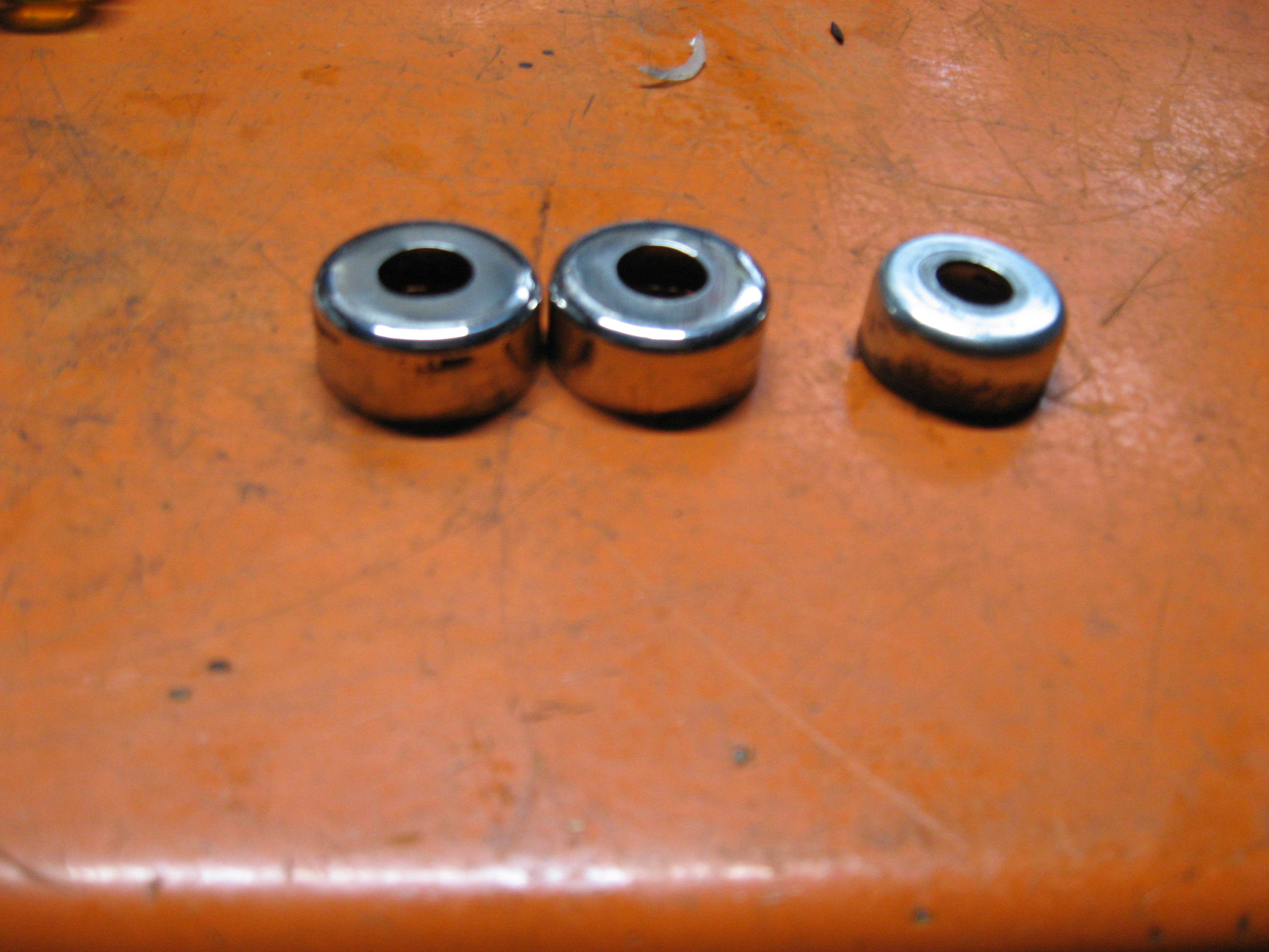
Then I went through my “O” ring kit and found one that the ID was just around the size of the threads.

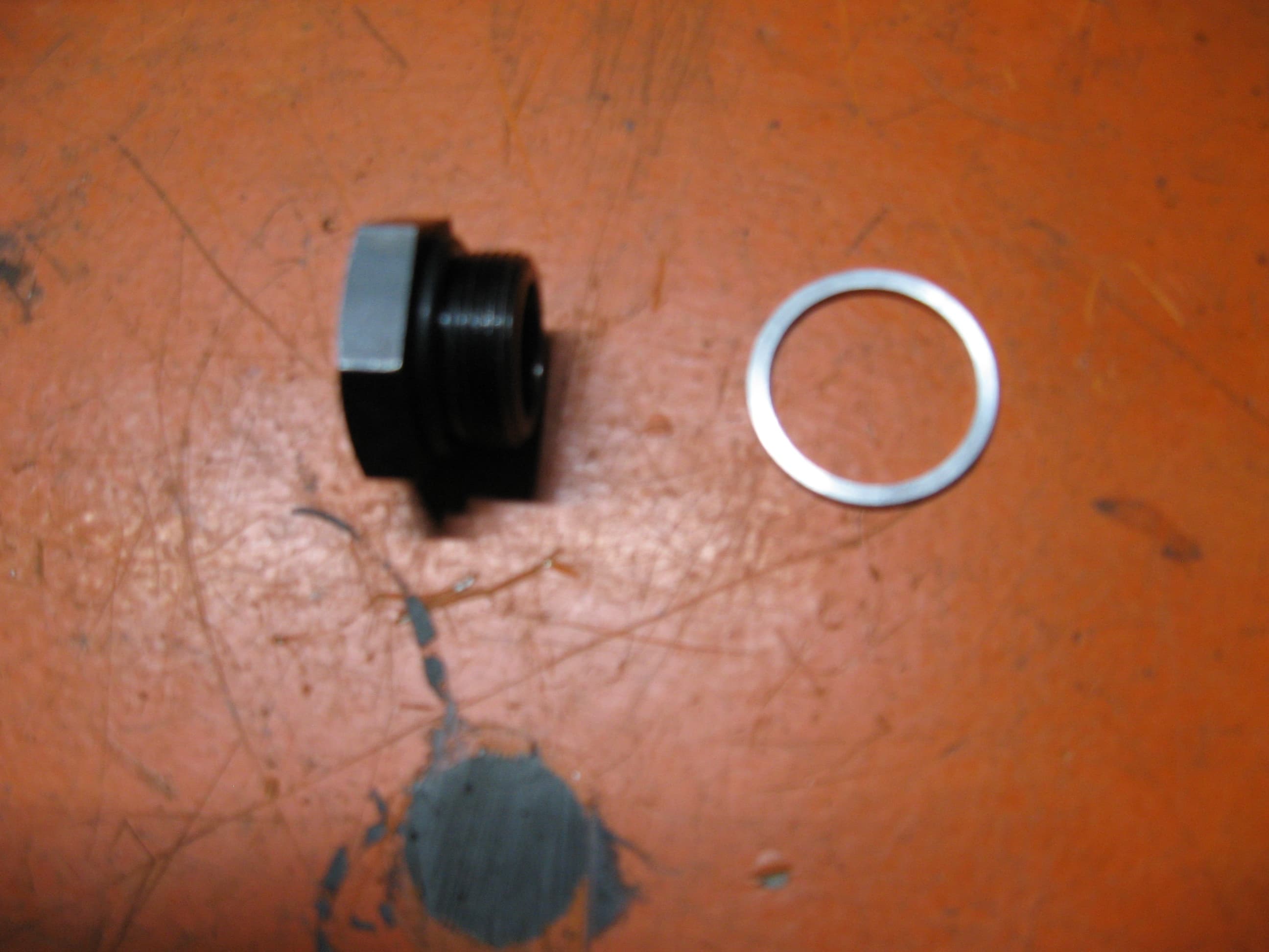
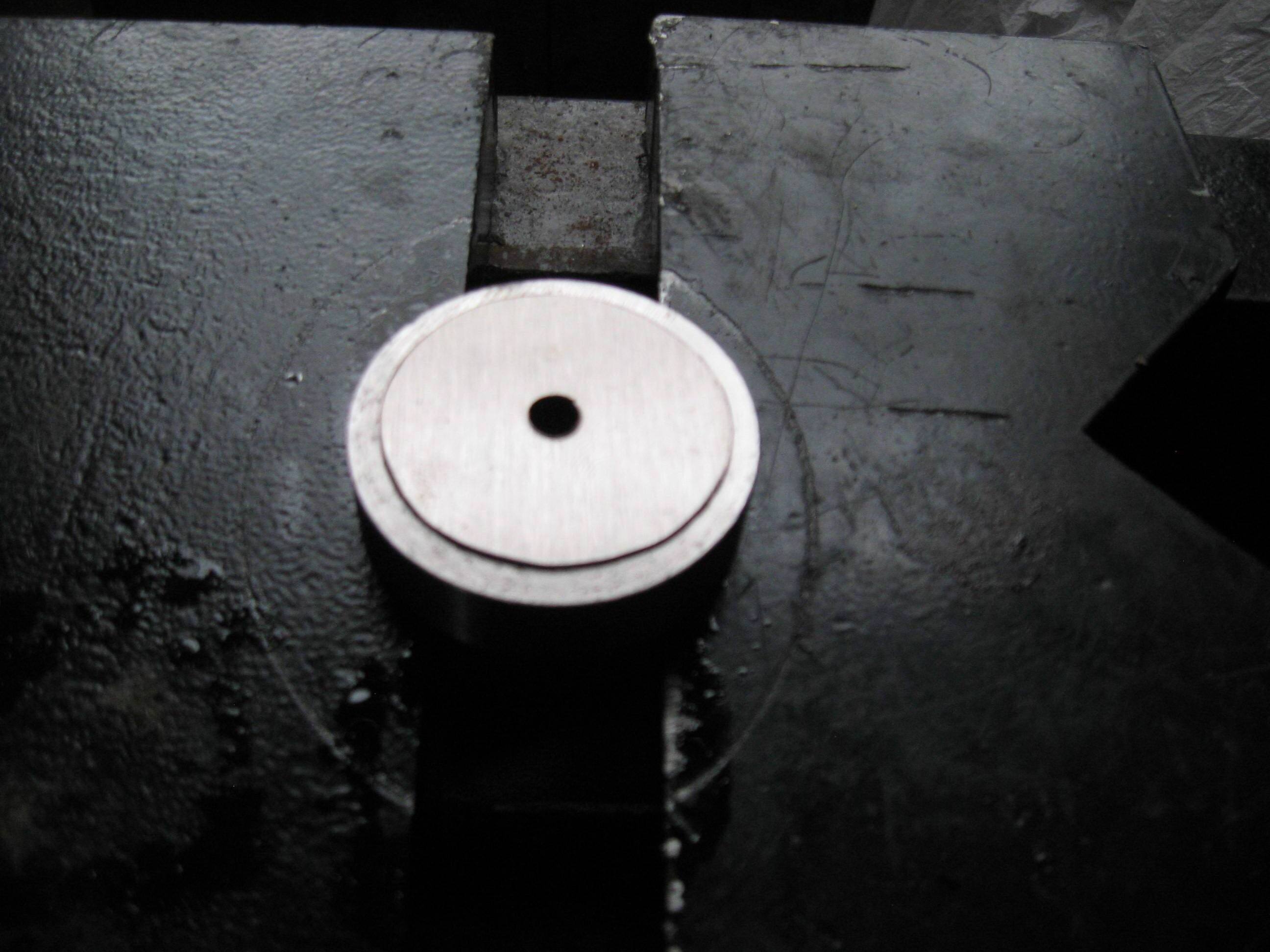
Next step was to make a ring (aluminum) that fit the outside diametre of the “O” ring.

And put it together. It fit nicely in the pan and appears that it is going to seal well. Worse case, make a new washer out of aluminum with no “O” ring to seal.

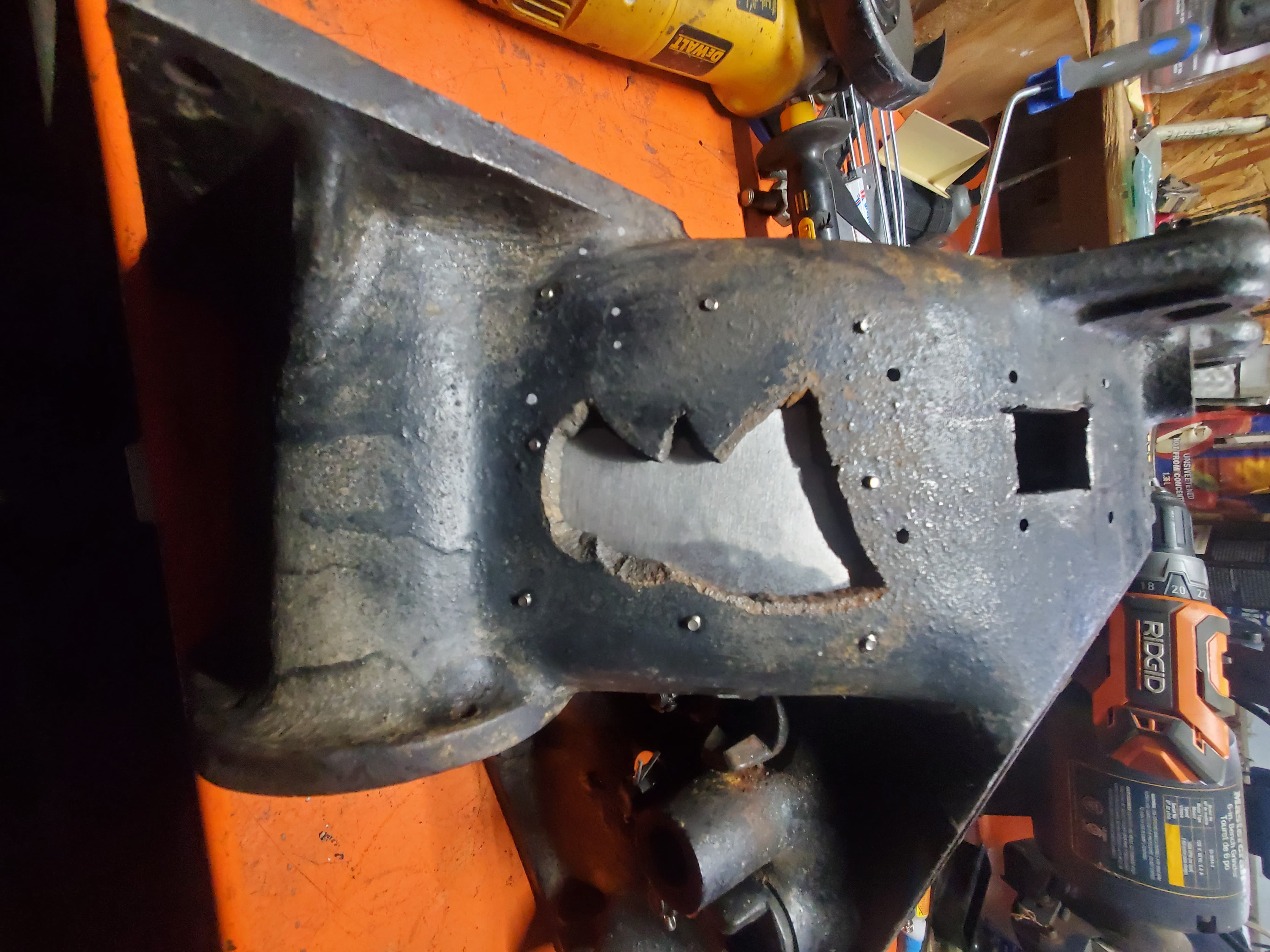
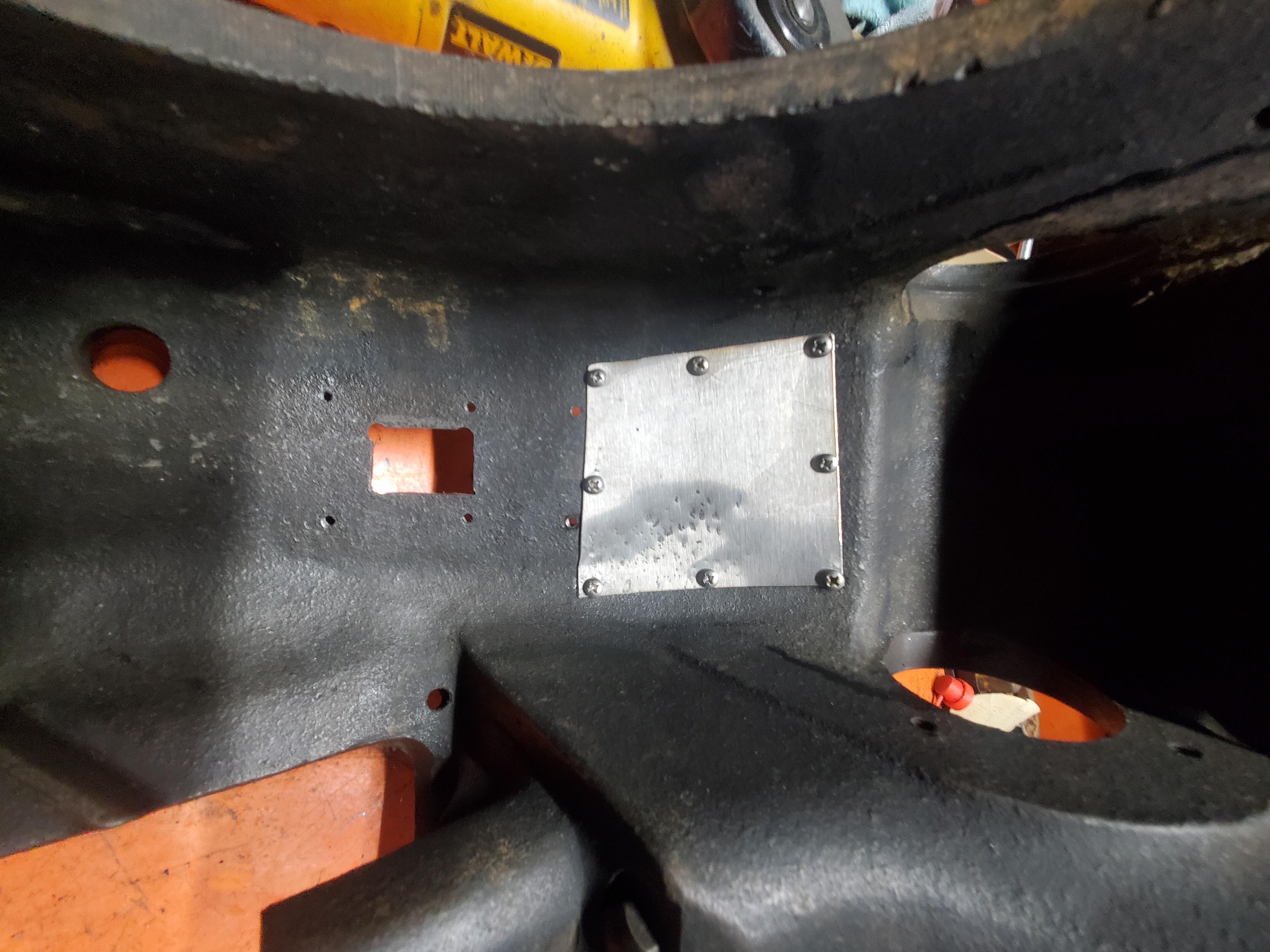
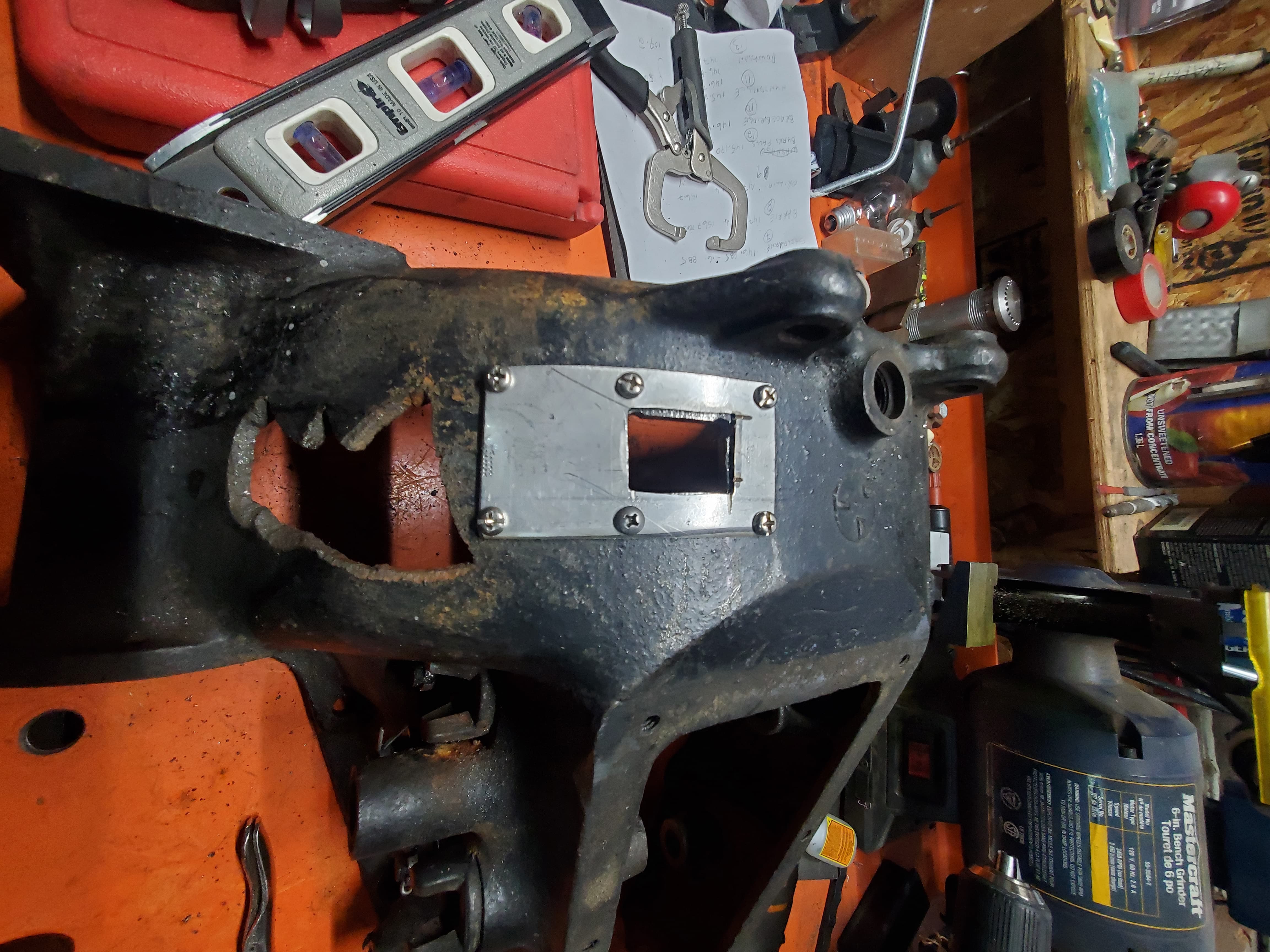
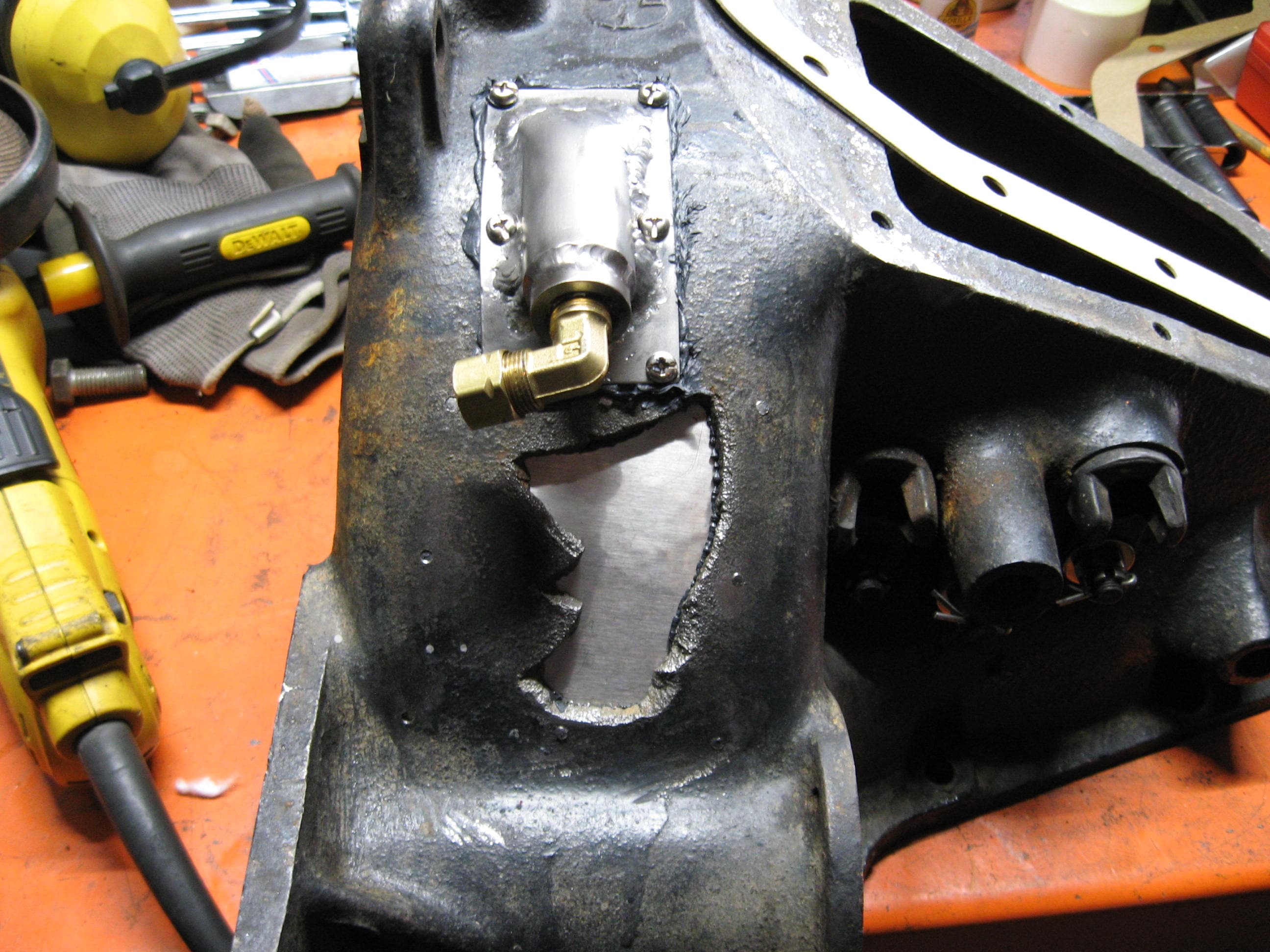
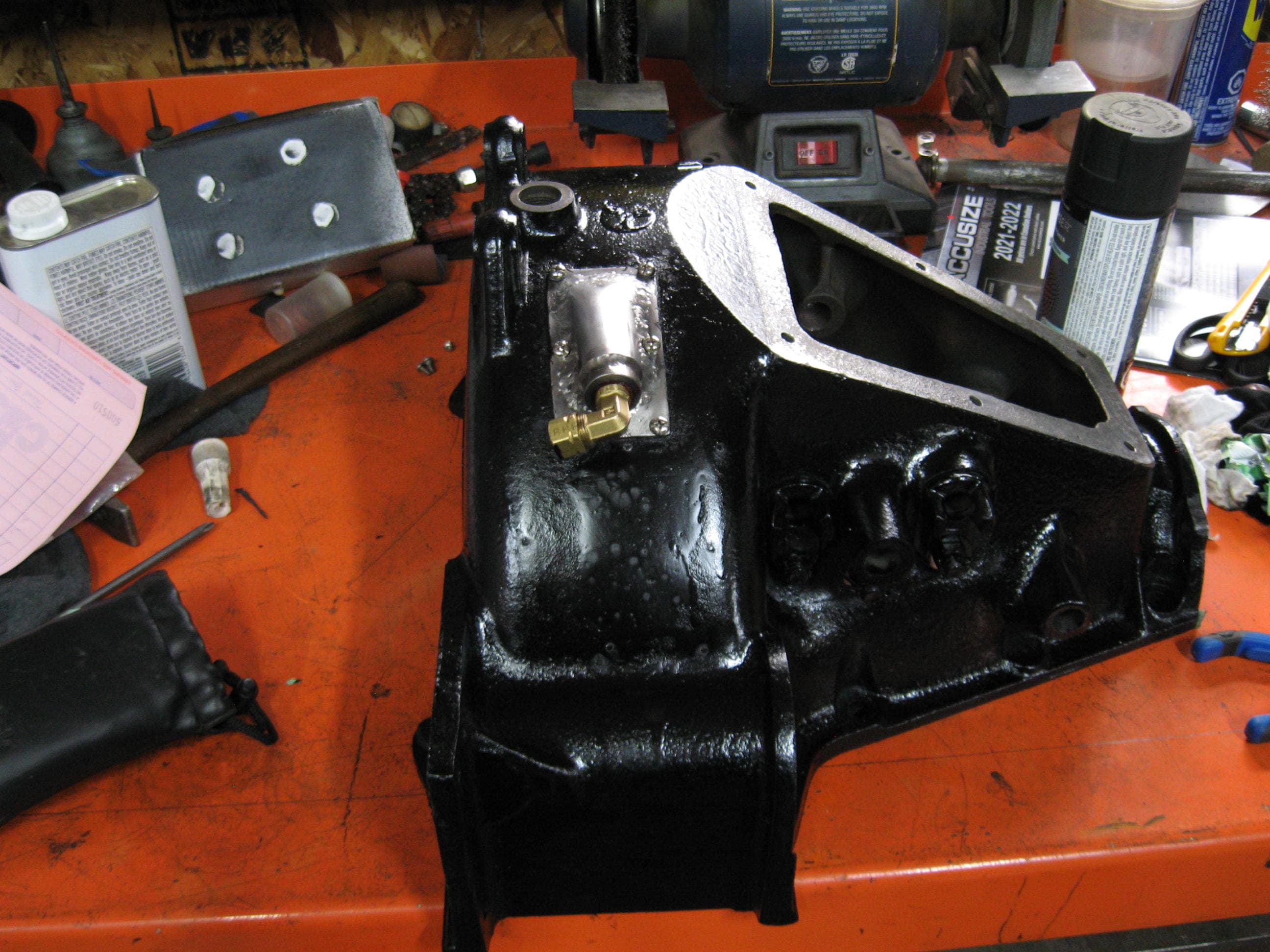
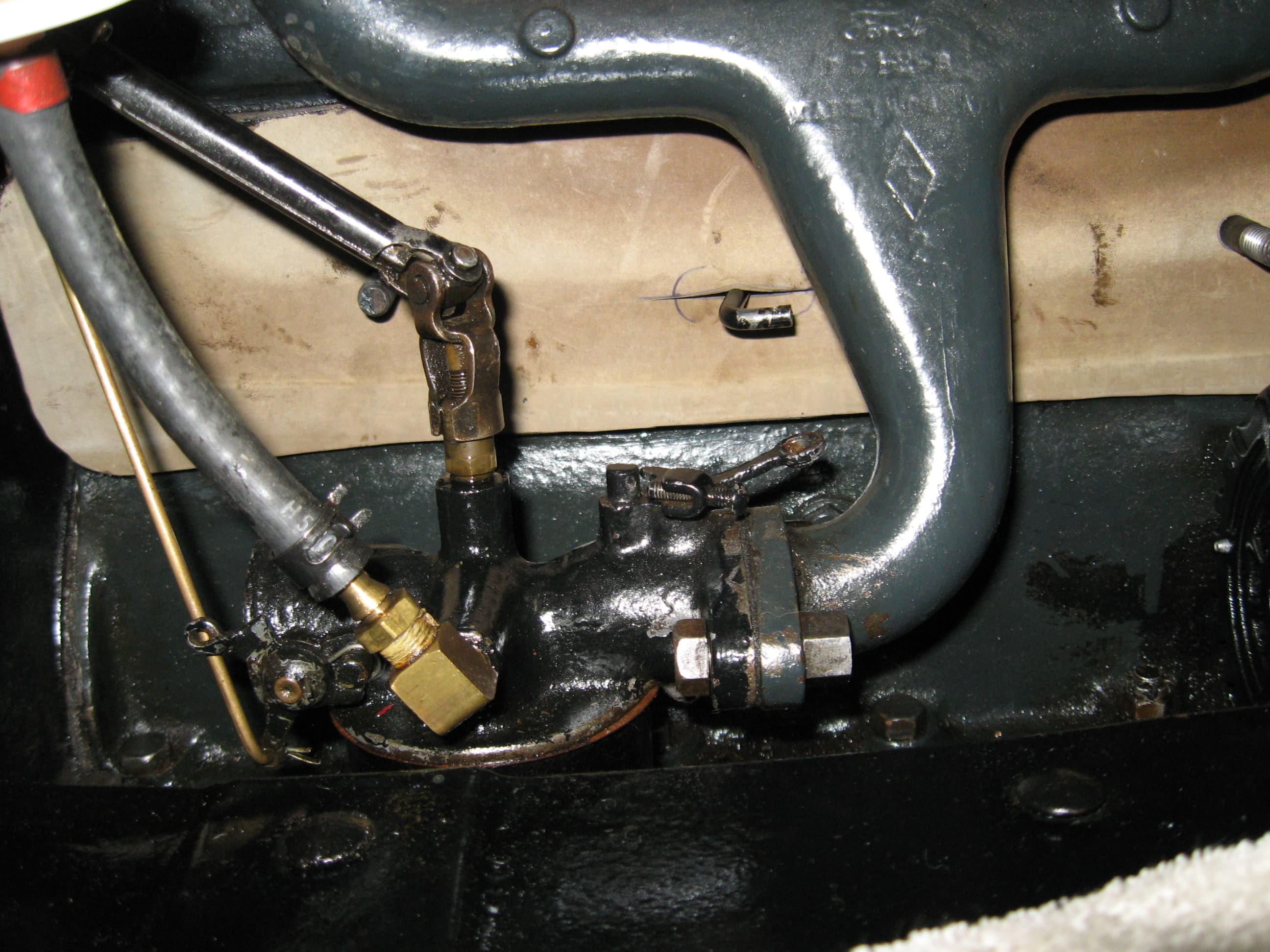
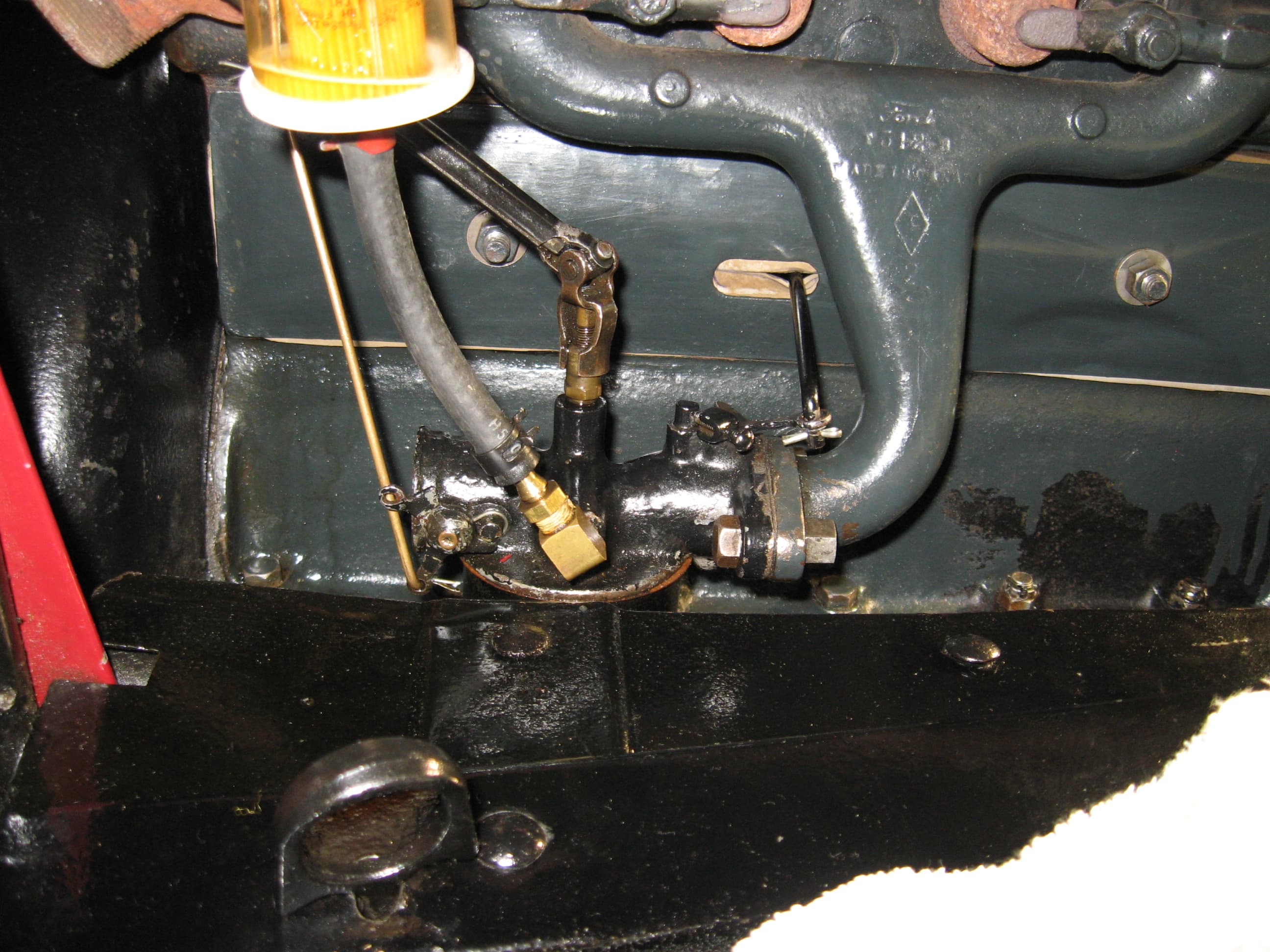
Next, I needed to reseal the valve cover as oil was leaking out where the throttle rod comes through, and could also see that the existing gasket had pretty much given up the ghost. Thought I’d try one out of rubber, but where the rod comes out, just cut a slit in the rubber to try and cut down on the oil that likes to come out that hole.

Here it is in place without the cover.

And done!

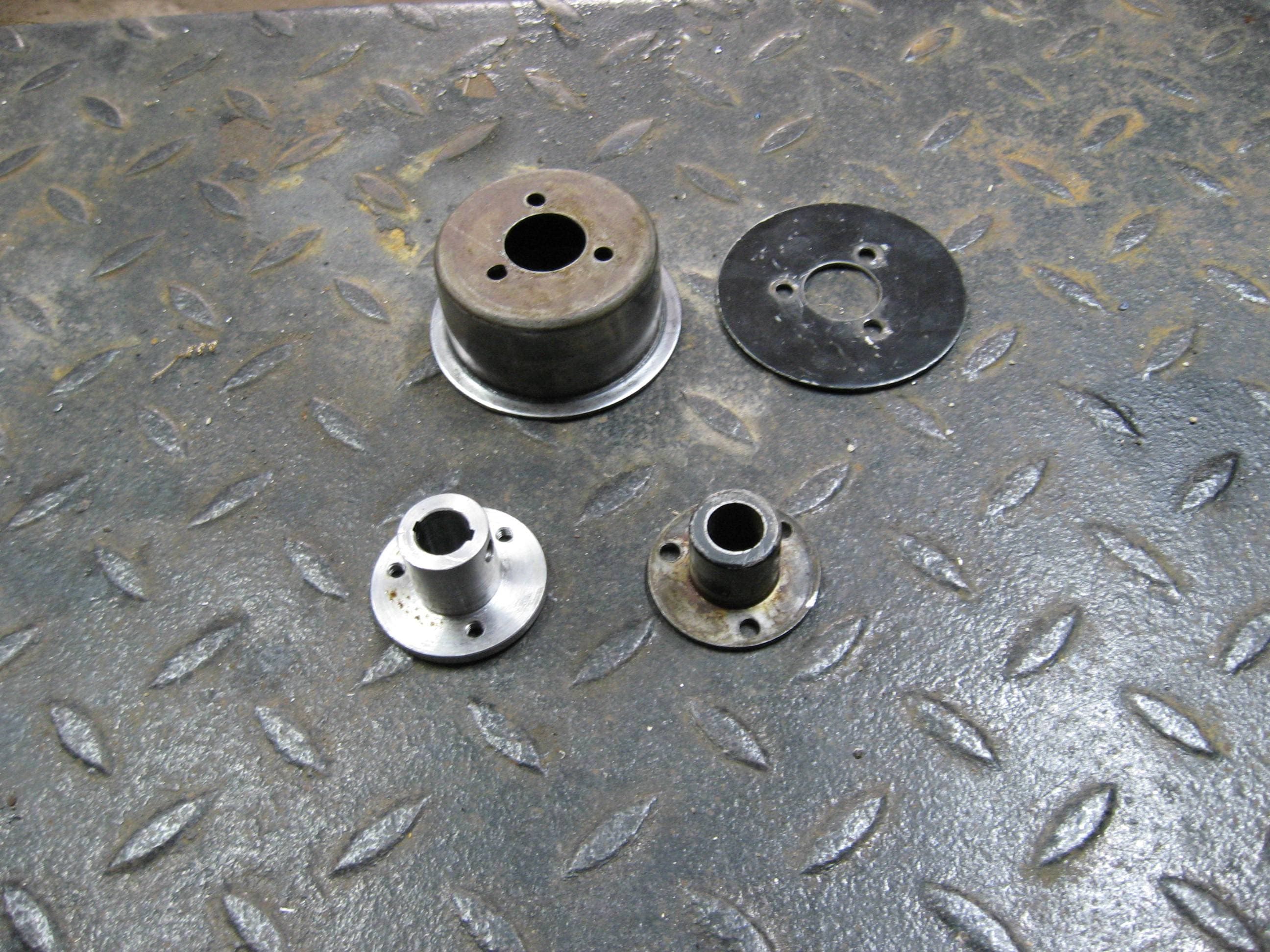
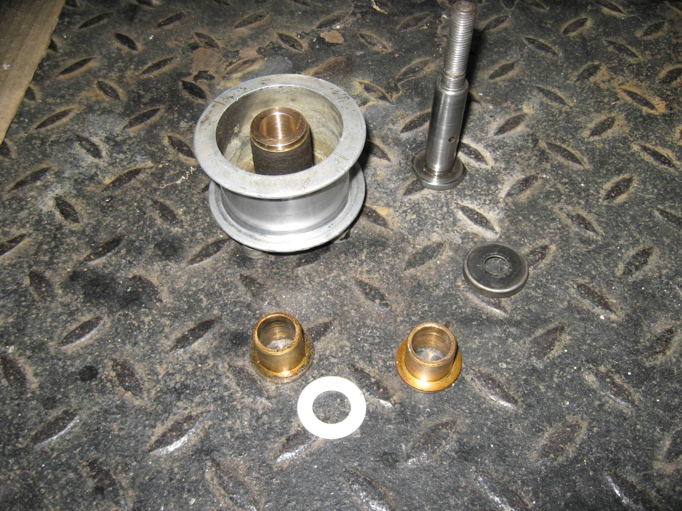
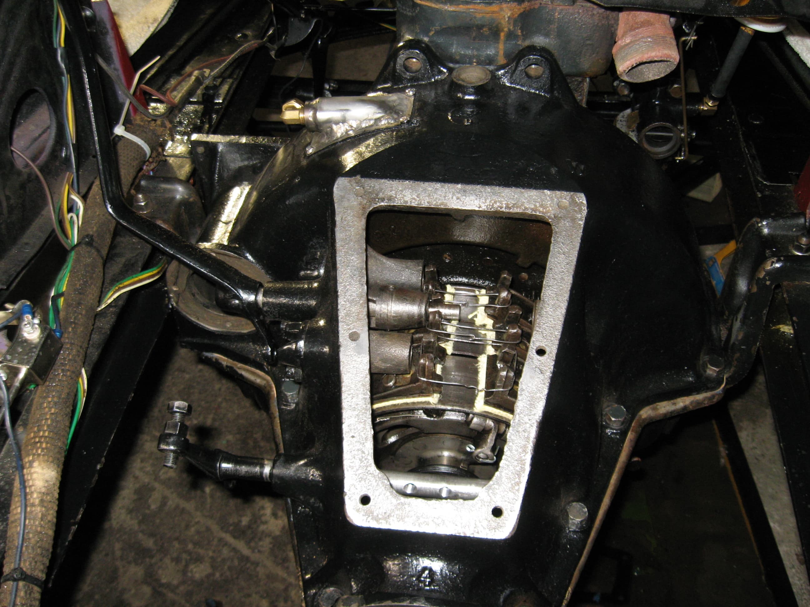
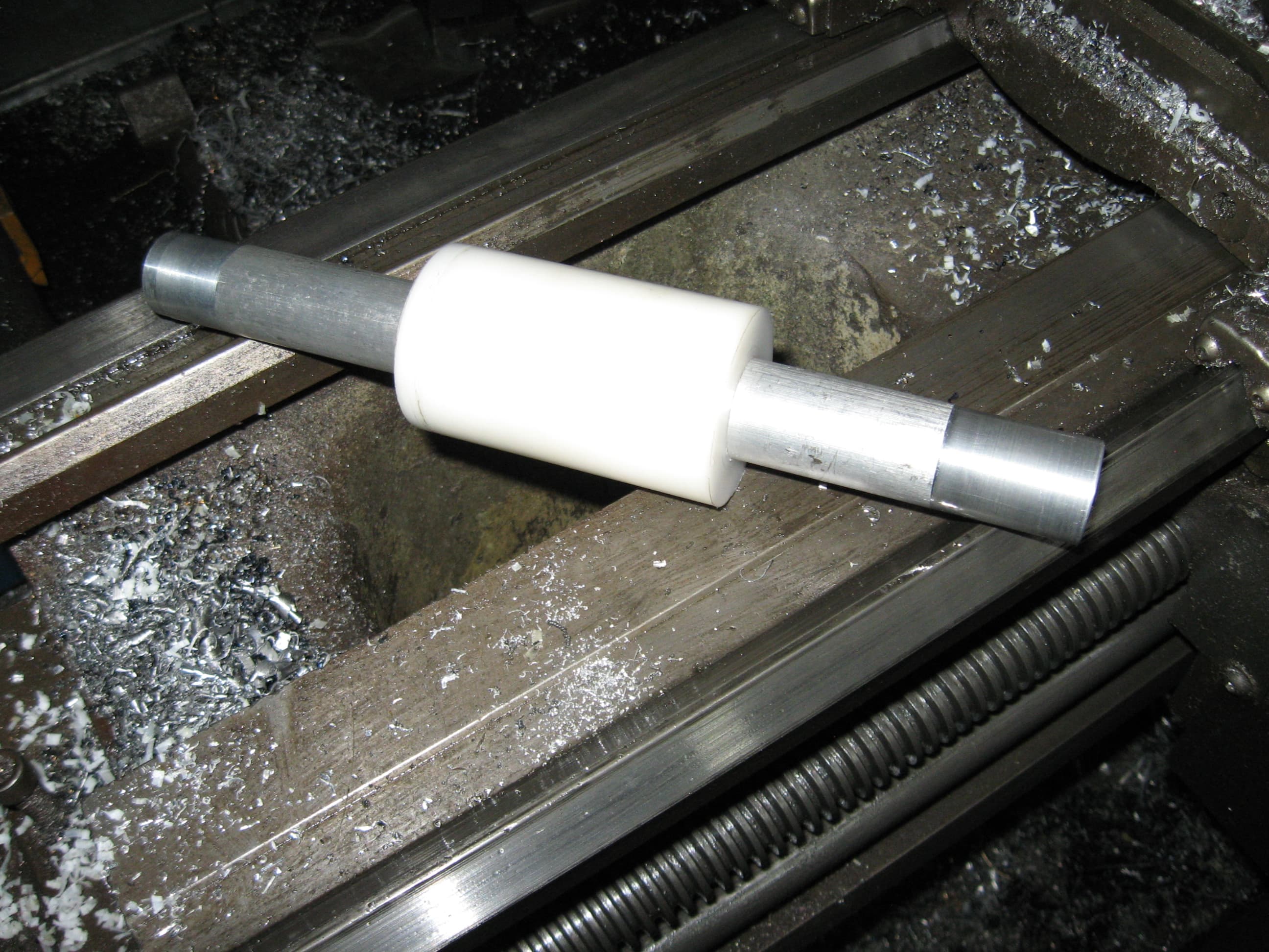
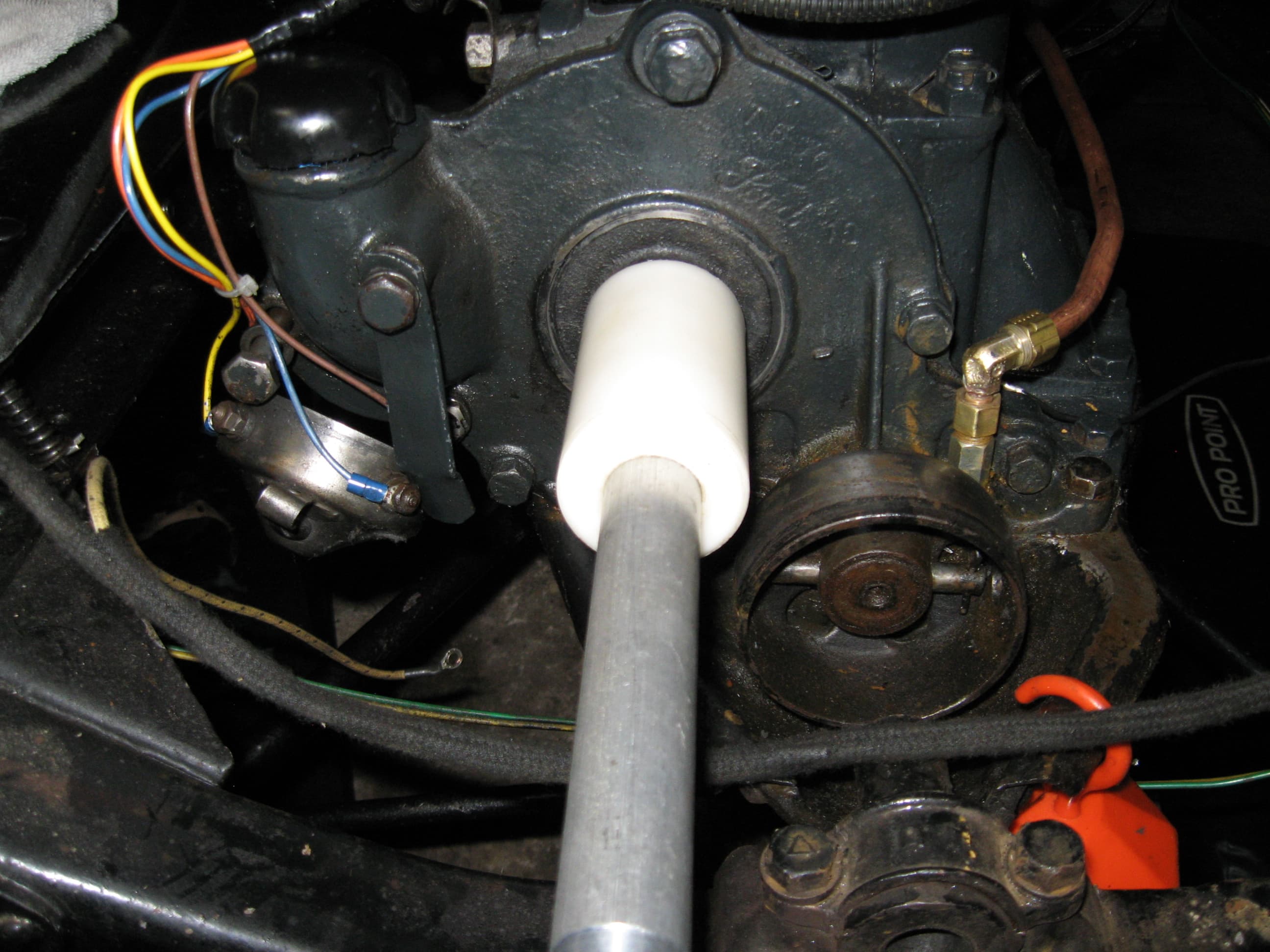
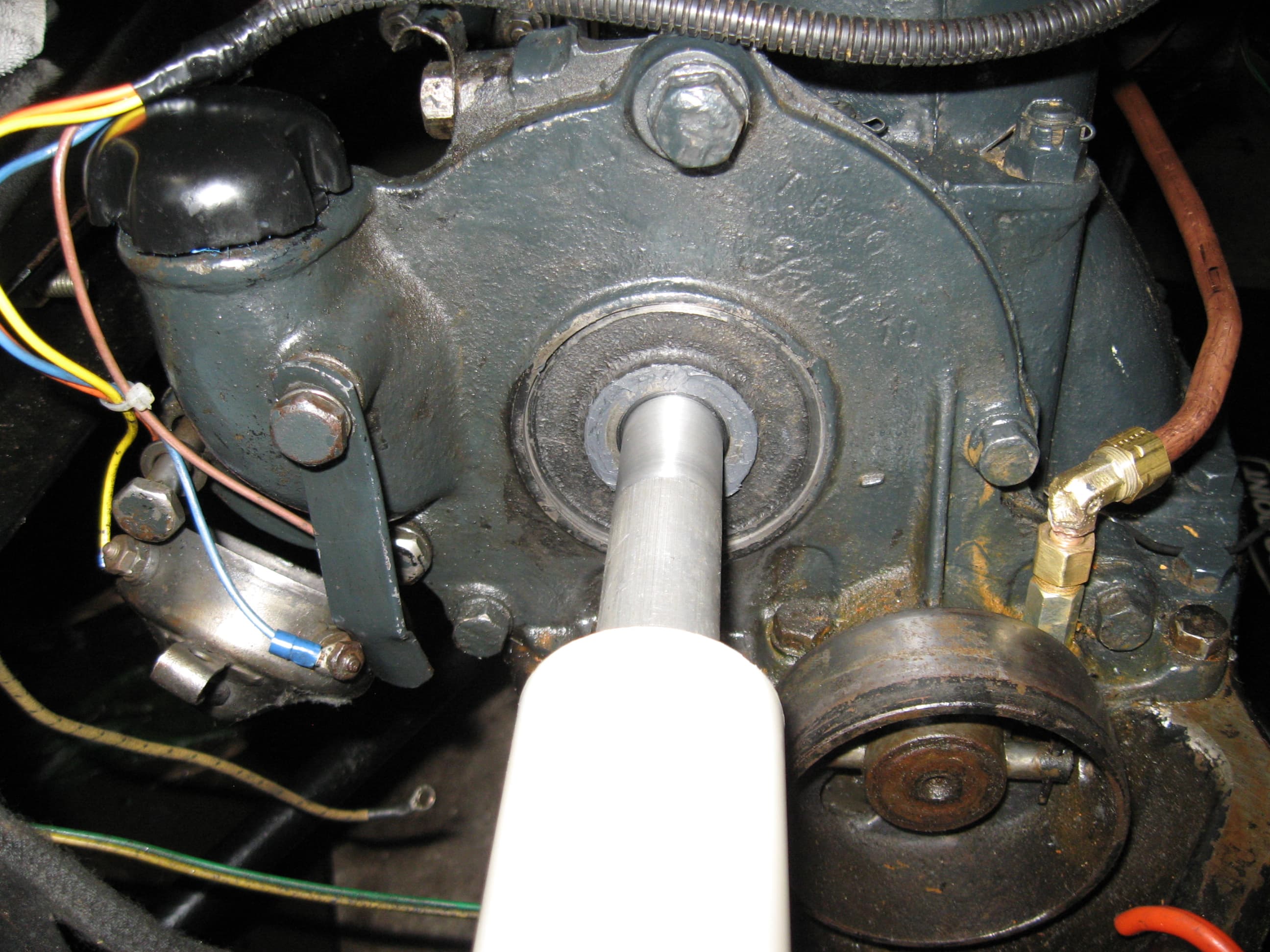
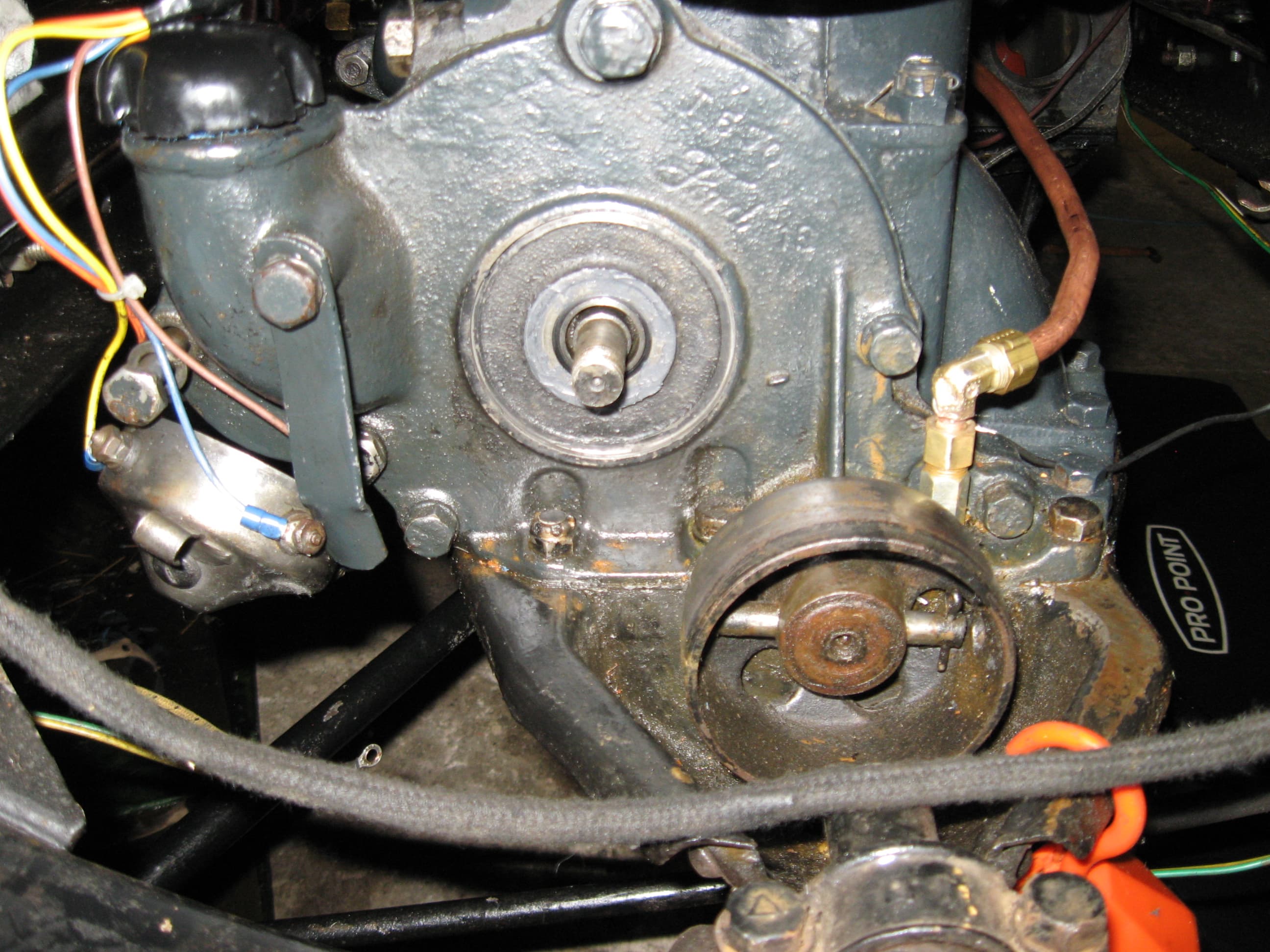
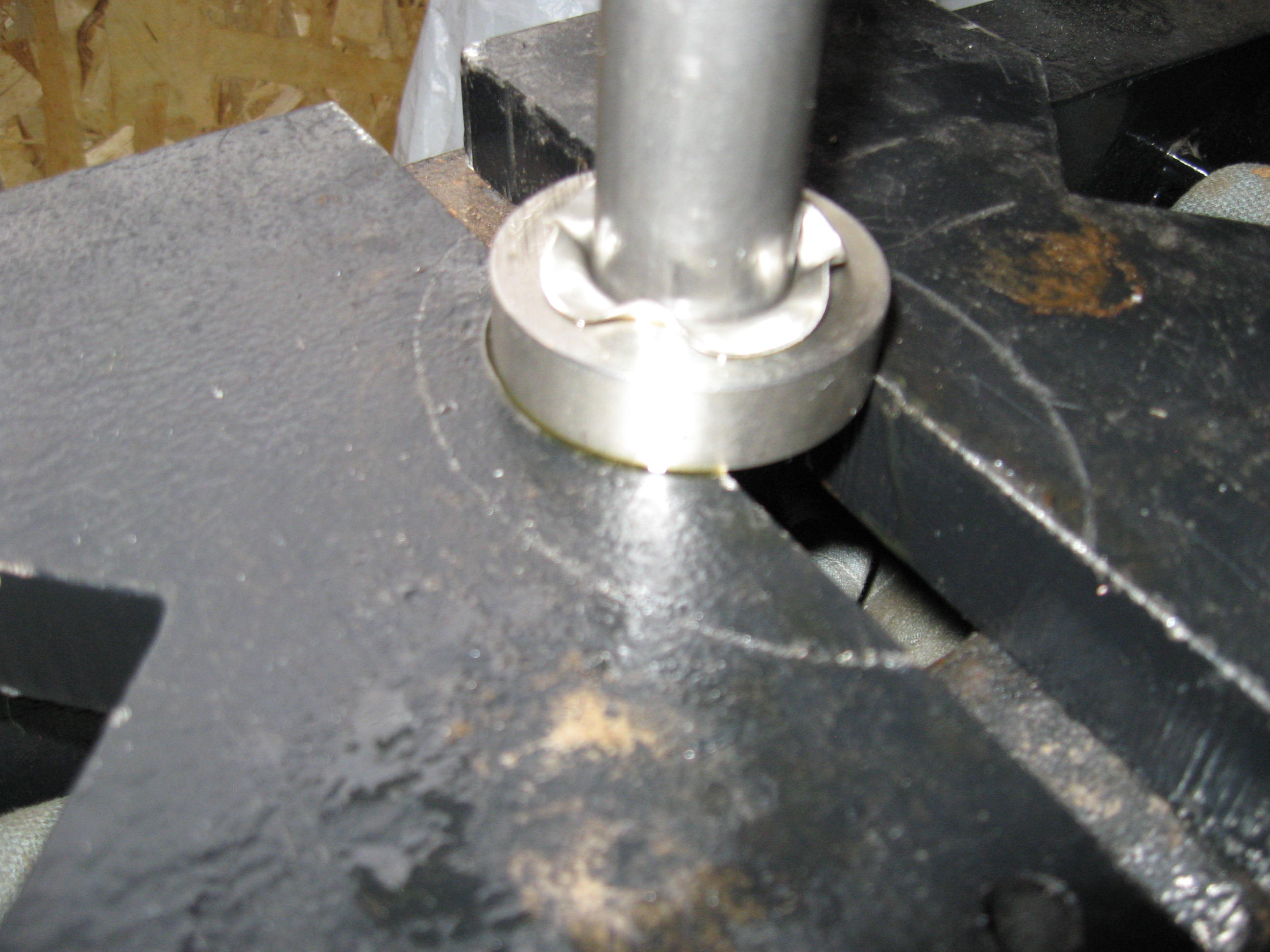
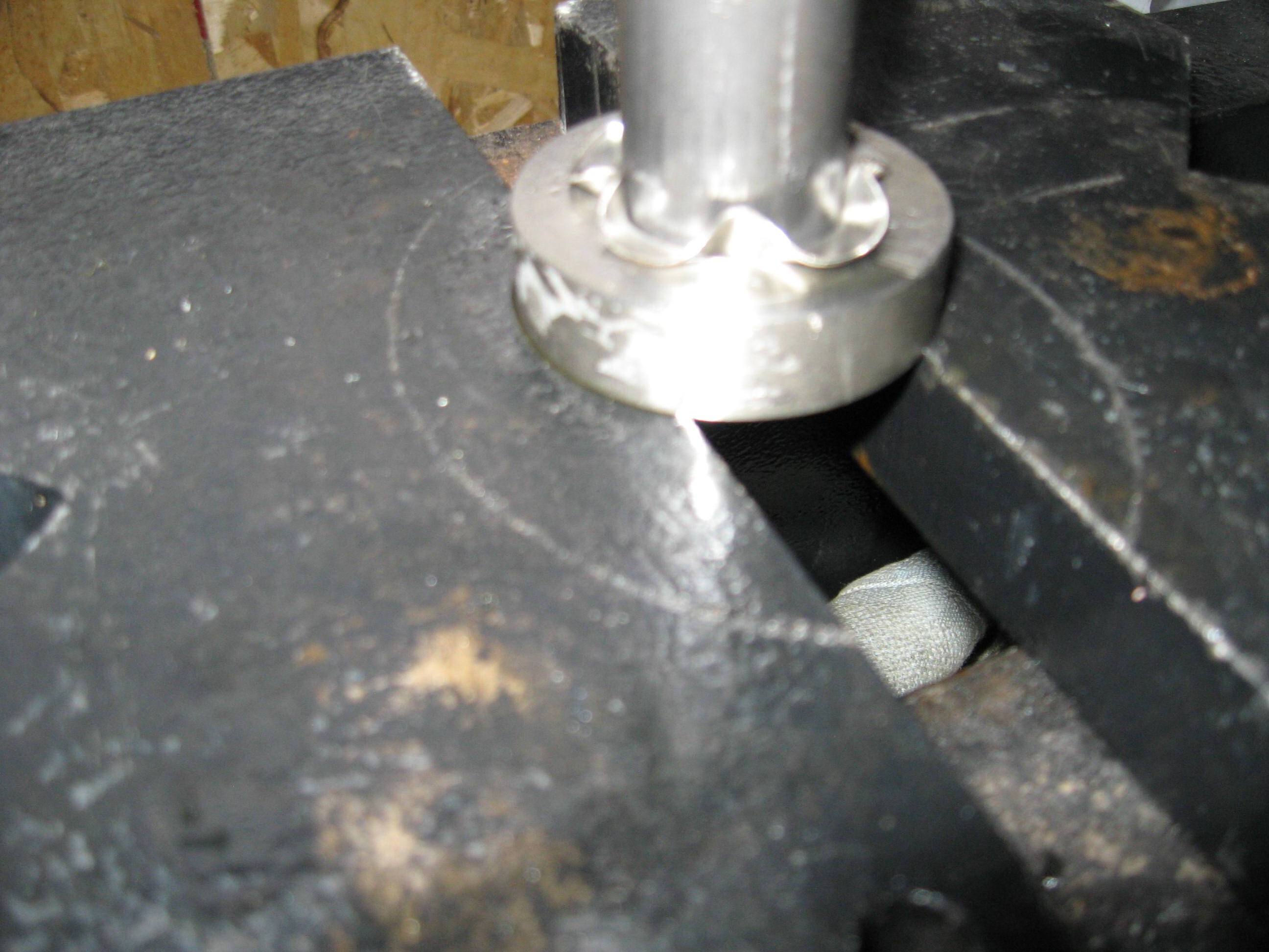
Next on the list is the New Day timer. It comes with a modern cam shaft seal to replace the tin cover and felt seal in behind. Problem is that Henry didn’t machine the area for a seal that didn’t exist. In the instructions they state that sometimes the seal fits other times not. Mine is a “not”. The instructions suggest using some RTV silicone on the outside of the seal to fill in the gap. (overall - .020 inch) My experience, regular silicone doesn’t like oil, so I used a silicone based gasket maker (SI 5900) I have used this stuff many time in my career as a Millwright with excellent results. But how to install a seal, trying to get the lip to go over the end of the shaft, without getting gasket maker all over your fingers. I made a mandrel out of a piece of 1” aluminum bar stock. (end of cam shaft is 1”) I cleaned up the bar and made it smooth so when I pushed the seal over it wouldn’t damage the lip. I had a plastic roller so I opened up the hole in the middle enough for it to slide, but not wobble, so it would push the seal straight.

Then I put a hole in the end of the bar that was a couple of thou larger than the end of the shaft along with a relief because there is a shoulder on the end that sticks out that would not let the bar go up against the end of the cam shaft.

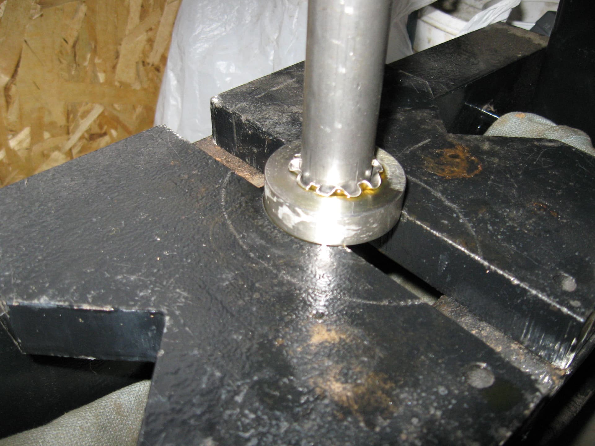
I put a very small amount of gasket maker around the bore where the seal is to go, and did the same to the outside of the seal. Put the bar over the end and used the roller to push the seal in to place.

The seal centres itself on the shaft and the gasket maker does the rest. Full cure time is 1 day.

You may notice the old timer hanging by some non-authentic looking wires. Absolutely! I had to make my own harness this summer. When I was cleaning the timer, the original harness fell apart. New one is hanging on the board to install. And the to-do list gets a little smaller.

Nice work. Good one!

Thank you! I appreciate your comment.

Hello all. More progress on my winter-to-do list that I’d like to share. I missed one thing back when I posted a picture of what I did with the valve cover gasket. I did the same thing on the other side of the engine where the throttle rod enters.

Next, the decorative covers that go on either side of the rad that are supposed to make the rad mounting look a little nicer are re-pops and I noticed that the cad plating on them was not so decorative anymore. You know, the white stuff when cad plating starts breaking down and rust. So I thought, before I just paint them, l’d try a fun experiment, and see if I can make my own so I machined a die and a punch.

I cut a disc out of .025 thick stainless using a hole saw and centered it on the die.

Then I took the punch and centered it to the die and used my press to give it a push.

The die is a little harder material than mild steel, but not hardened like a die, so I hoped I could get 2 pieces pushed through. The second one gave me some grief to get it through the die without blowing out the bottom, but with some finesse, I was able to get a second disc pushed through, but the die is done, but served it’s purpose. The 2 on the left are the ones I made, and I polished them with a buffing wheel in my drill press.

An unexpected addition to the list but needed to be done. And the to-do list stayed the same…lol

Edit -2 hours or so later: Have been reading a lot on this forum, it’s been interesting and informative. Thank you to the person who initiated it.

Keep up the good work you’ll be up & running soon. Best John

Thanks John. Its been fun tweeking the car, correcting some issues that have arised. It will also be nice to have the list finished. Then wait for the snow to be gone and get the car back on the road for another summer of cruises and just going for a drive.

Nice work. Maybe some grease on the dies would help.

Thank you, appreciate the compliment. I had a lot of oil on the die. Now, that being said, I used cutting oil thinking that might be the thing to use considering the process. In hind sight (always 20-20) grease (EP properties), or engine oil may have been better, not having a forming or drawing oil just kicking around…lol. As you can see in the pictures, the stainless wrinkled as I pushed it through. The first one went through with ease, but the wrinkles scored the die. I polished it as much as I could without changing the dimensions too much to get a good forming on the second one, but I think the scoring created some serious drag. If I ever try something like this again, I will use the same material for the die, but will try a hardening process (whole thing or surface). The only drawback to that is making it too hard so that it’s brittle and it blows apart under pressure.