I have the green service book, but not a manual. The book I have does not state anything about doing a magnet recharge. I have a small compass and have watched videos of other the people doing it. If memory serves, place the compass about 1" down from the mag post and about 1" to the left. Then line up the north pole of the magnet with the compass. My assumption is that that lines it up with the coil. Do the flash. If someone is willing to send me a digital copy of the actual procedure from the manual, please pm me and I’ll pass on my email address.
This might help:
https://modeltfordfix.com/recharging-the-model-t-ford-magneto/
Thanks. I have read that article. It is informative. I am not going to be removing the engine, so plan is to do an in car recharge.
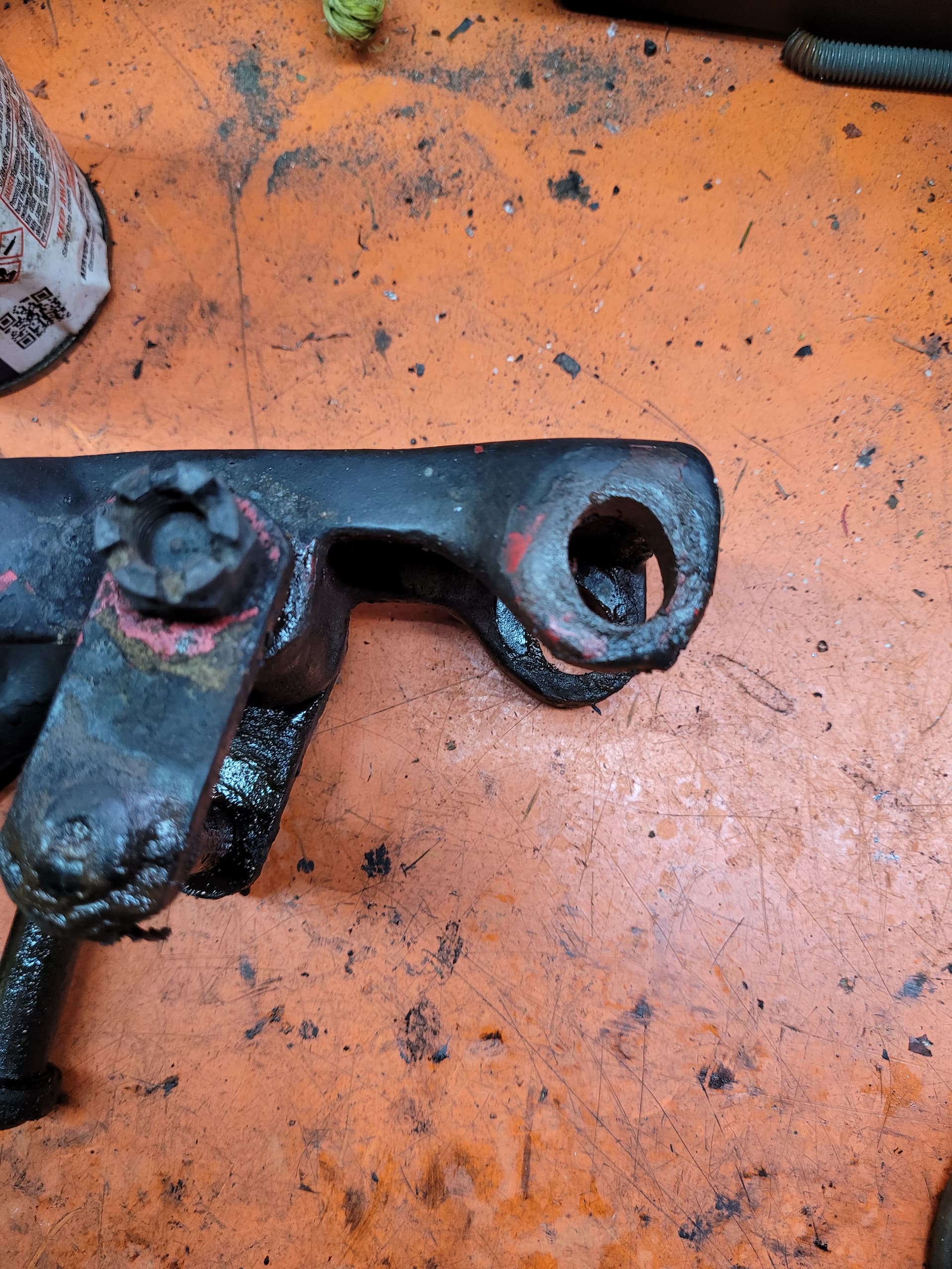
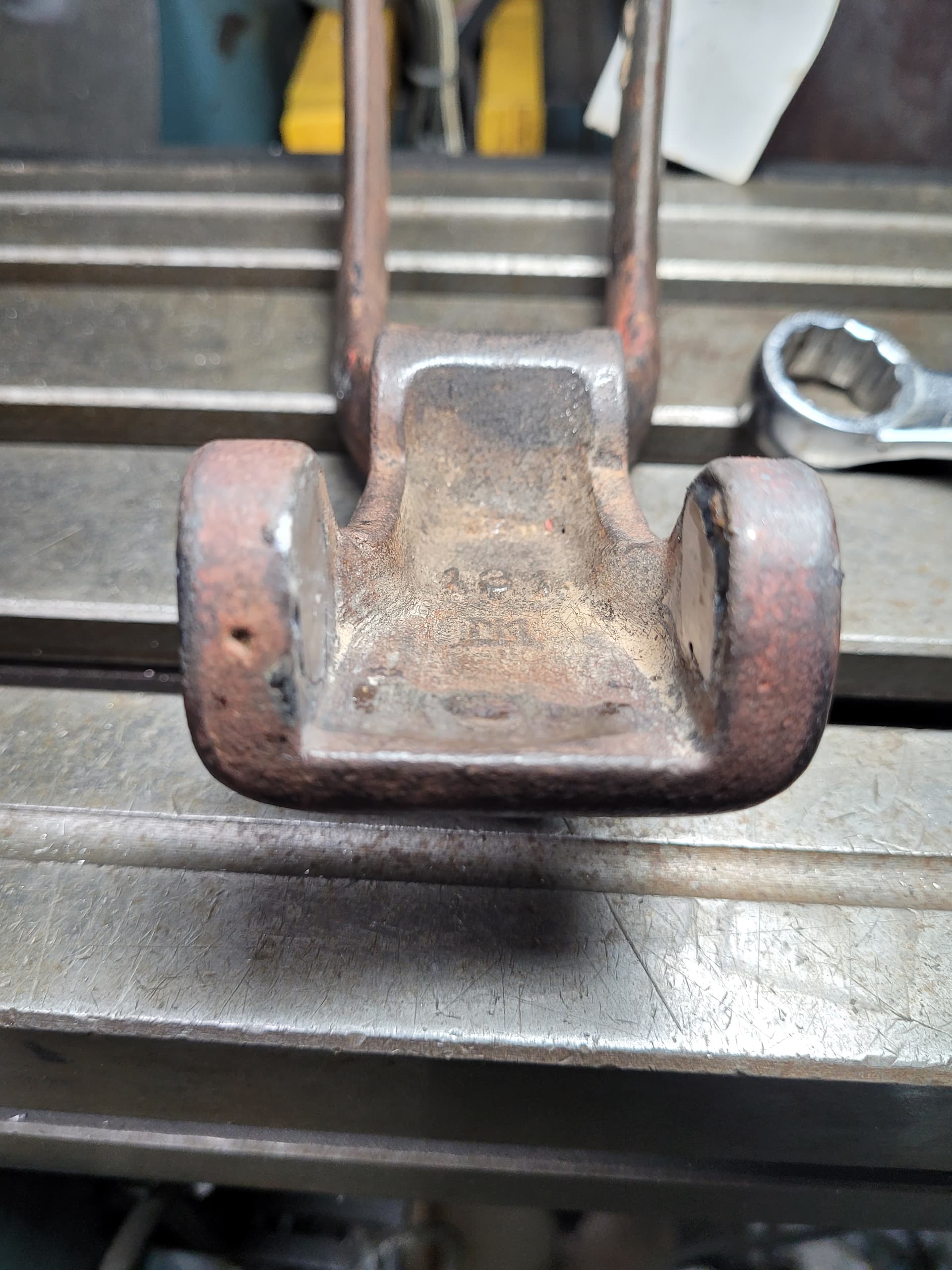
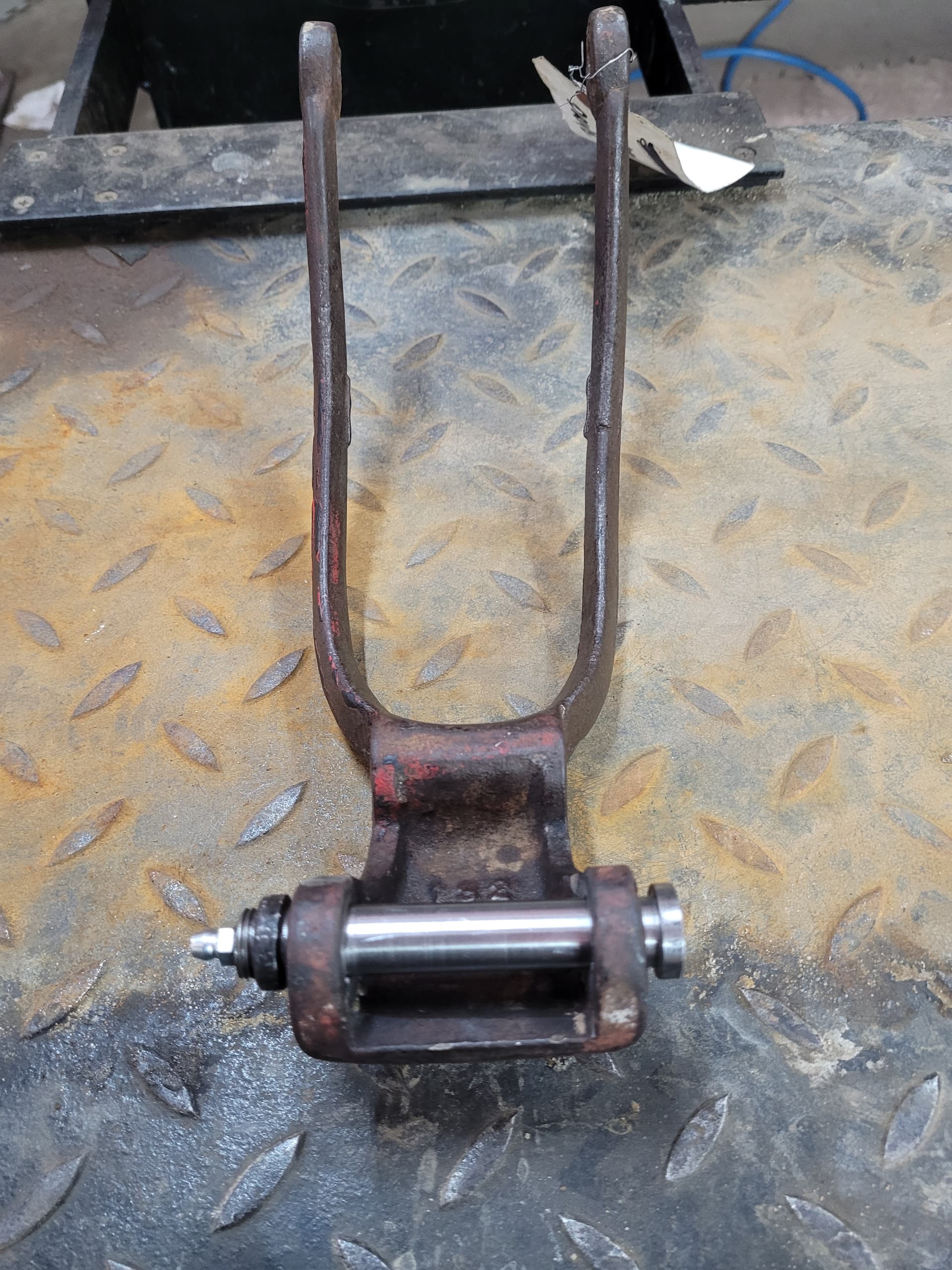
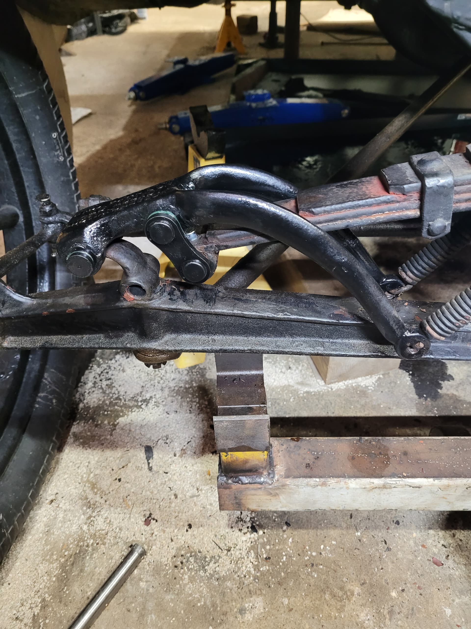
The winter to do list for the 19 has started. The rad is out and was taken to, I think from research, just about the only recore shop in Ontario Canada. They were going to have to fabricate a complete rad and by the way the conversation went, it appeared to be less expensive to order one from the part suppliers in the US. Removed the Richard Wilcox shock absorbers to address wear. They are the same as W&C double arm shock absorbers. The plan is to measure where the center of the hole is supposed to be and weld the hole closed and machine it out to the correct size. As you can see, its quite worn. All 4 are like this. If you look at the pictures of the car near the beginning of the thread, you will see them on the car. Have to replace rear wheel bearings as I think they might be originals. They were well greased but also well worn. Also reline rear brakes as the material is done, but also whom ever did it last, installed the rivets backwards. So the fun has begun.
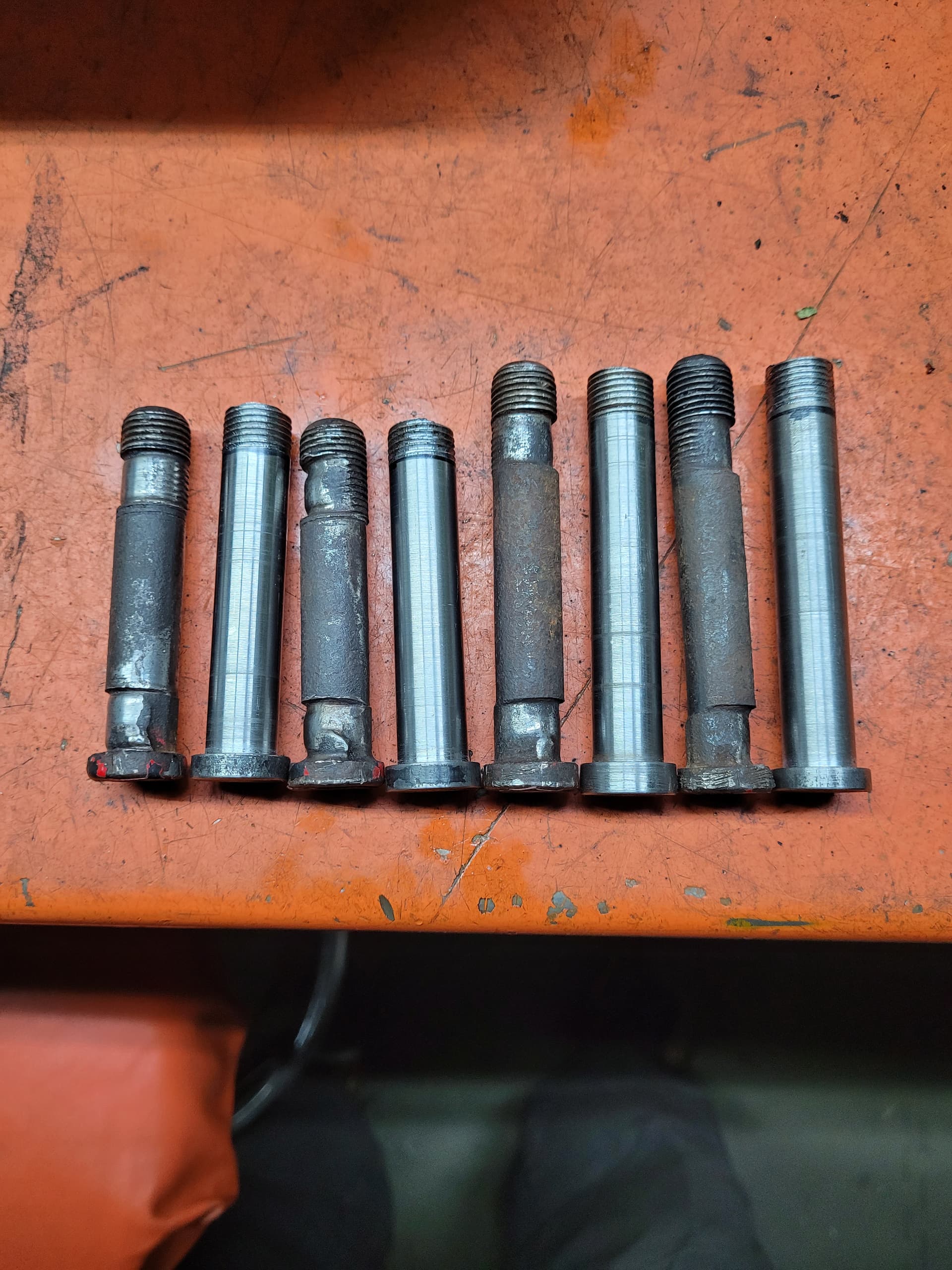
4 new pins fabricated from 3/4" bar stock, turned down to 9/16" with 9/16 fine thread on the end like originals.
Also removing several layers of paint from the arms. Appears as if the original color was red.
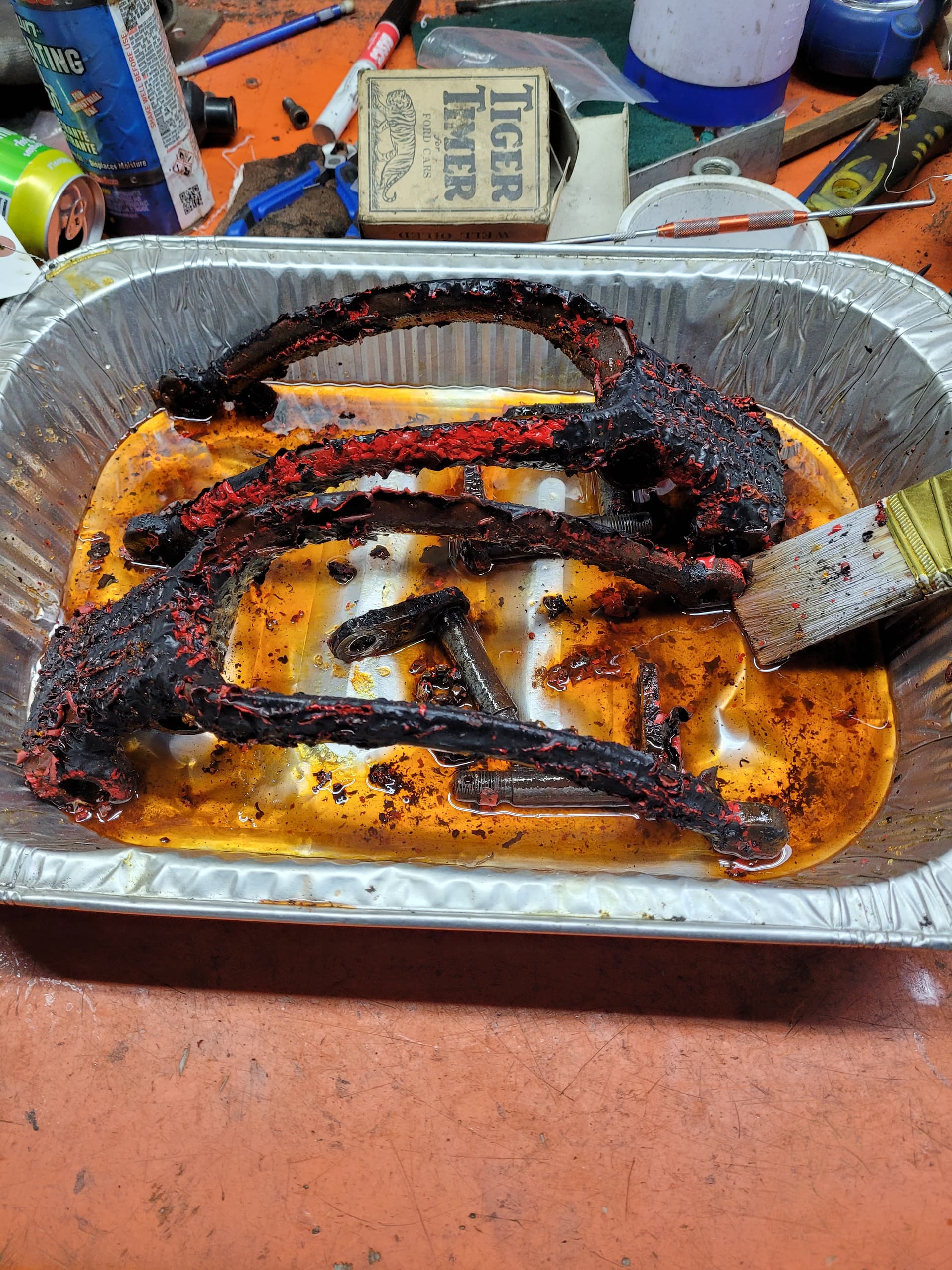
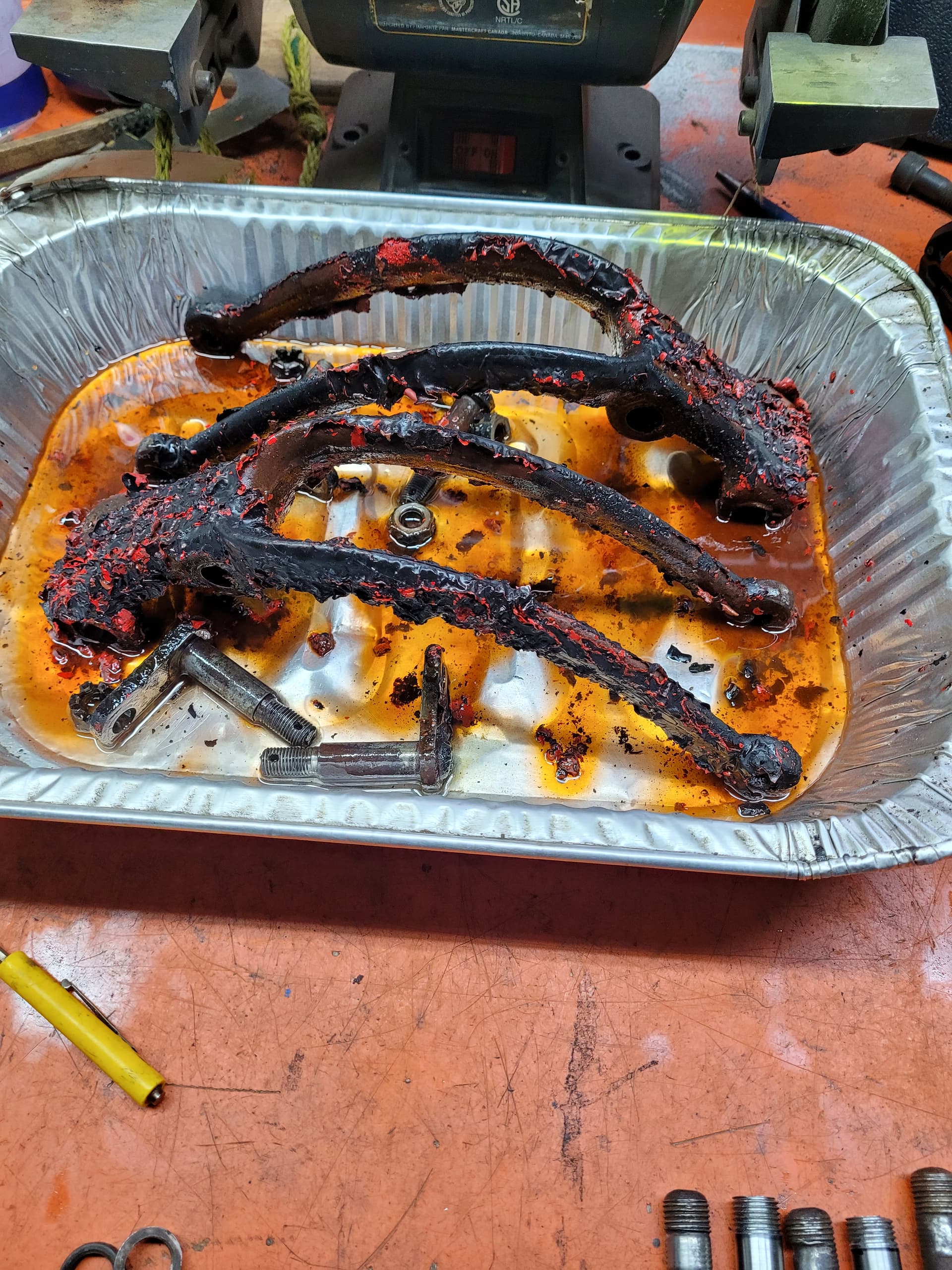
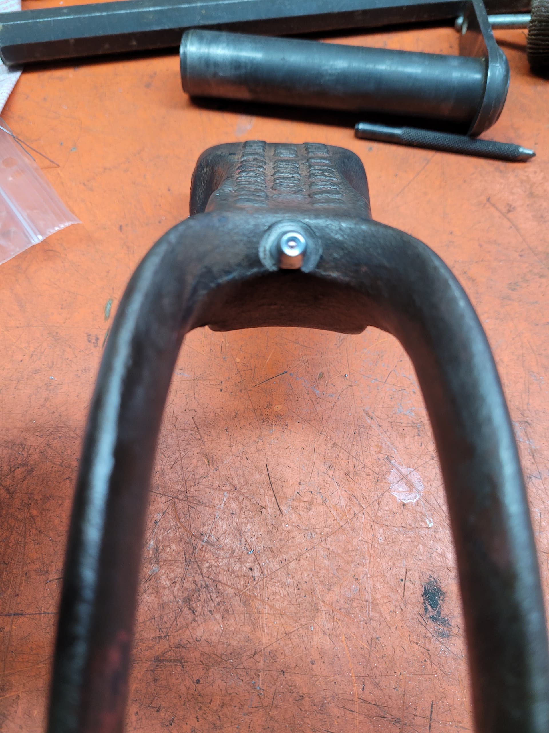
The arms cover the oil holes in the perch, so I was trying to figure out how to lube them. A 4 A.M. epiphany ![]() ! Pins got spun up again in the lathe and drilled some grease holes. One would think that that should have come to light when making them
! Pins got spun up again in the lathe and drilled some grease holes. One would think that that should have come to light when making them ![]() .
.

Nice work! Excellent in all respects.
Thanks Auto_Inn. Appreciate the compliment.
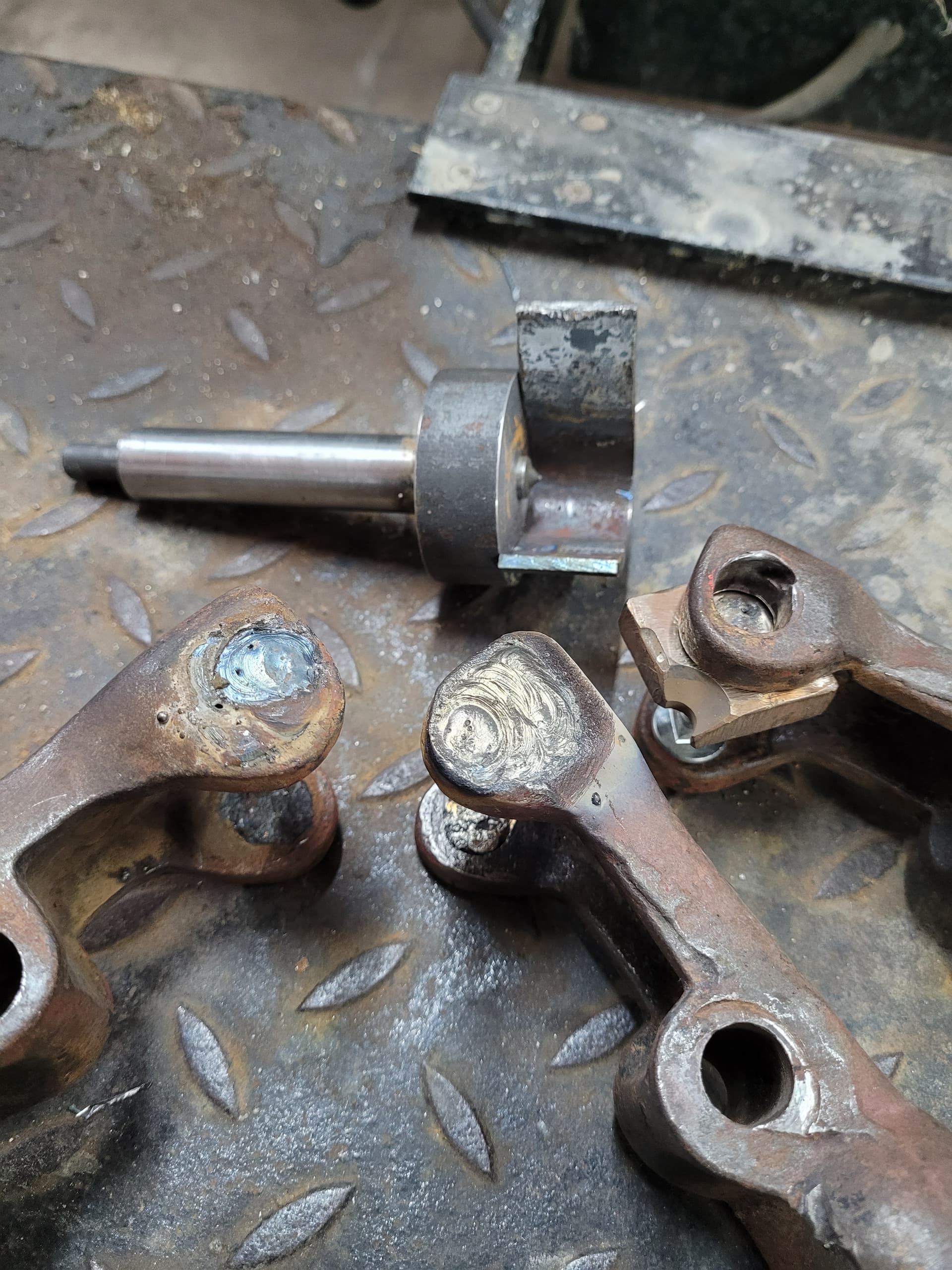
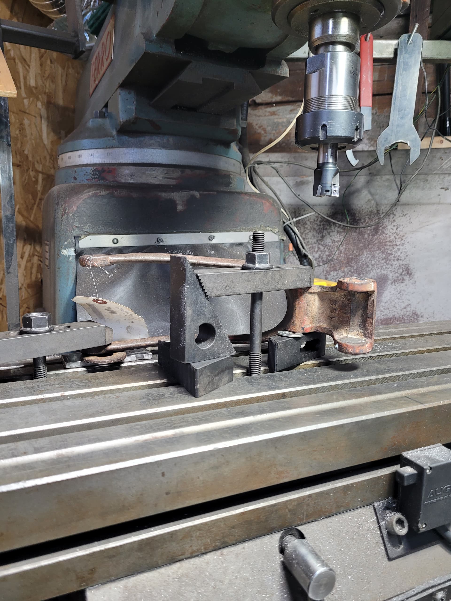
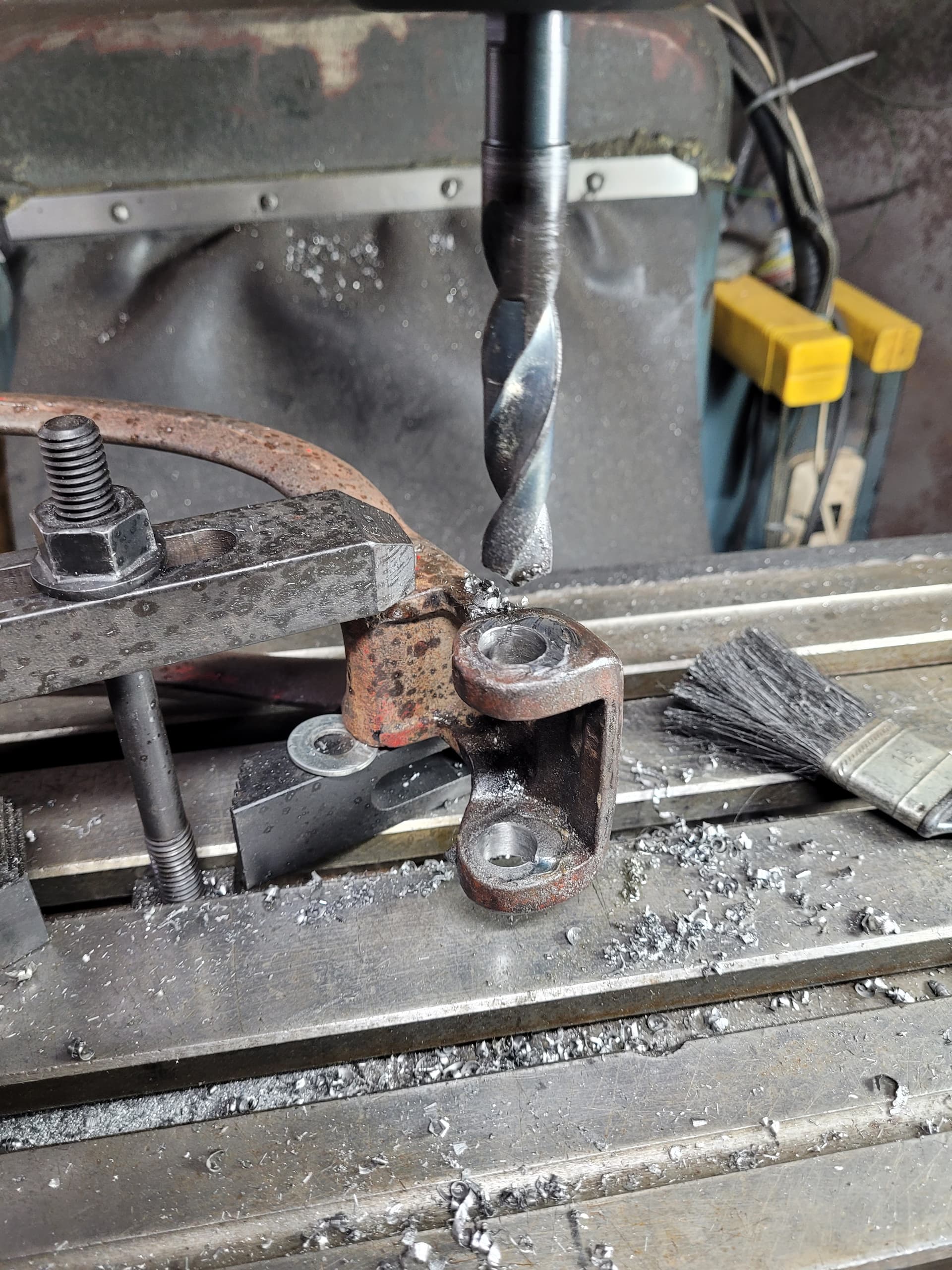
T parts have arrived so it’s back to the grind on the 19. Could have been working on the shocks but something else, as always, came up. I have plug welded 2 of the arms where the pin goes in and through the perch. As you can see a couple of pictures back, the holes are very worn. The one on the right is my set-up for welding. A piece of brass held in place with a nut and bolt. Tedious and time consuming. Weld a bit, clean all the flux out to prevent a crater and weld some more. Rinse and repeat. In the upper left, you can see a jig I made, after some careful measuring, to put the hole for the pin in the correct spot. The round piece sits on the welded surface and the piece of flat bar goes around the ear of the arm to position the jig correctly, then stike the punch to mark where to drill. When I get the that point, I’ll show the set up in the milling machine.
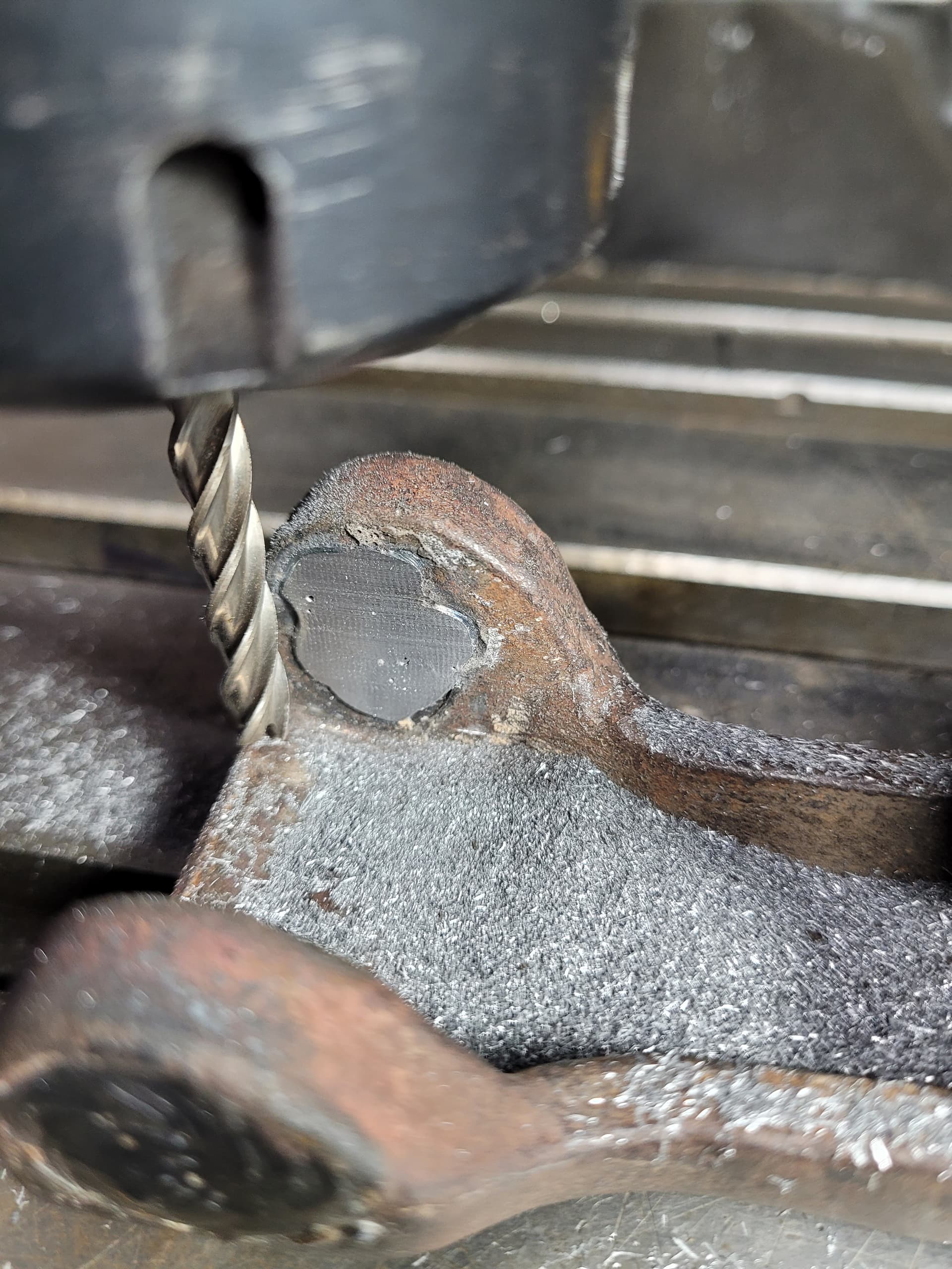
Hello all. Finished plug welding the holes, used a die grinder to remove some brass residue on the inside and added a layer of weld. Set up the arm in the milling machine to clean up the inside. First picture is before I started, 2nd is part way through and the 3rd is both sides done. Have to do this to the other 3 and then set up to drill holes.
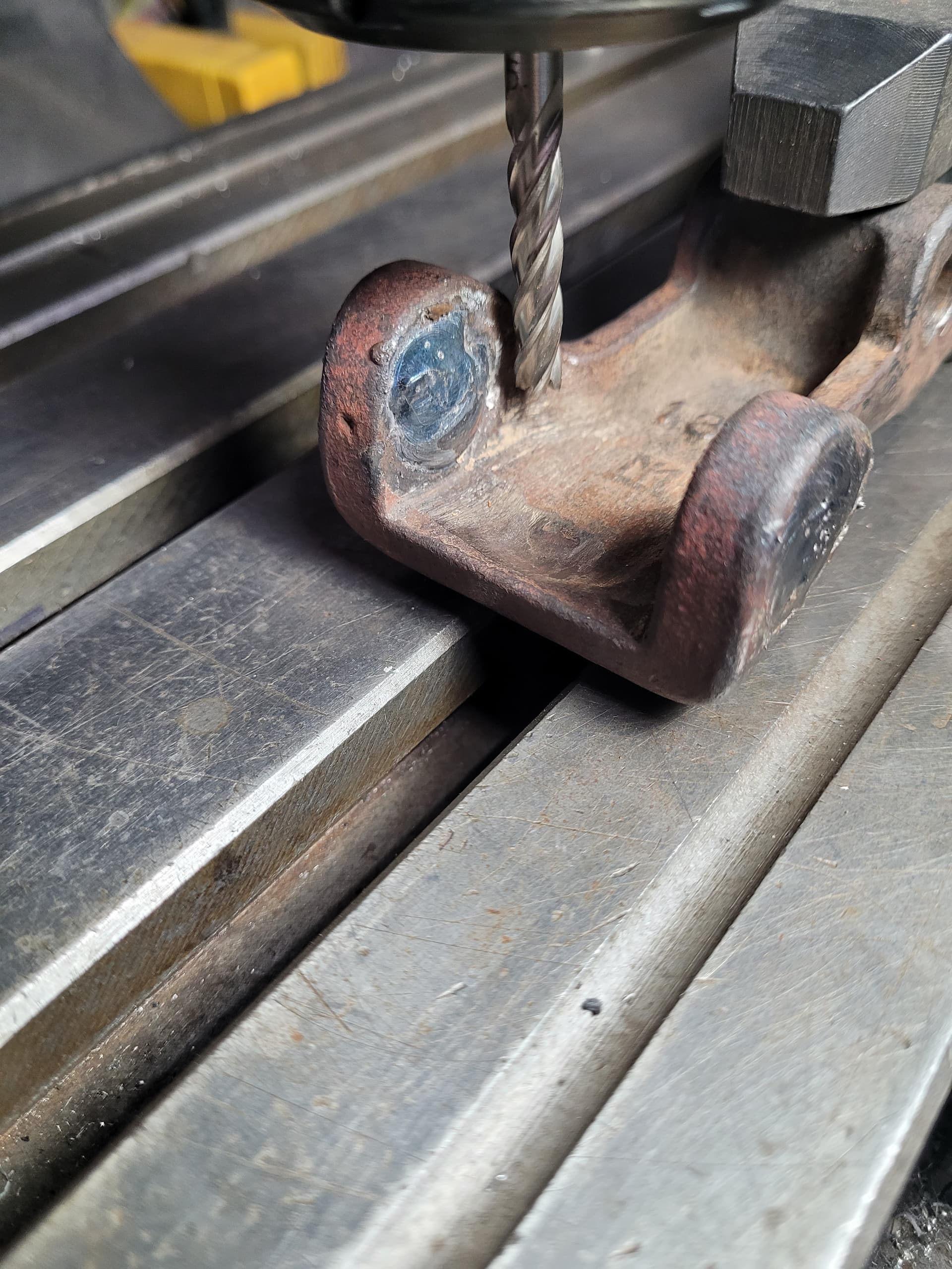
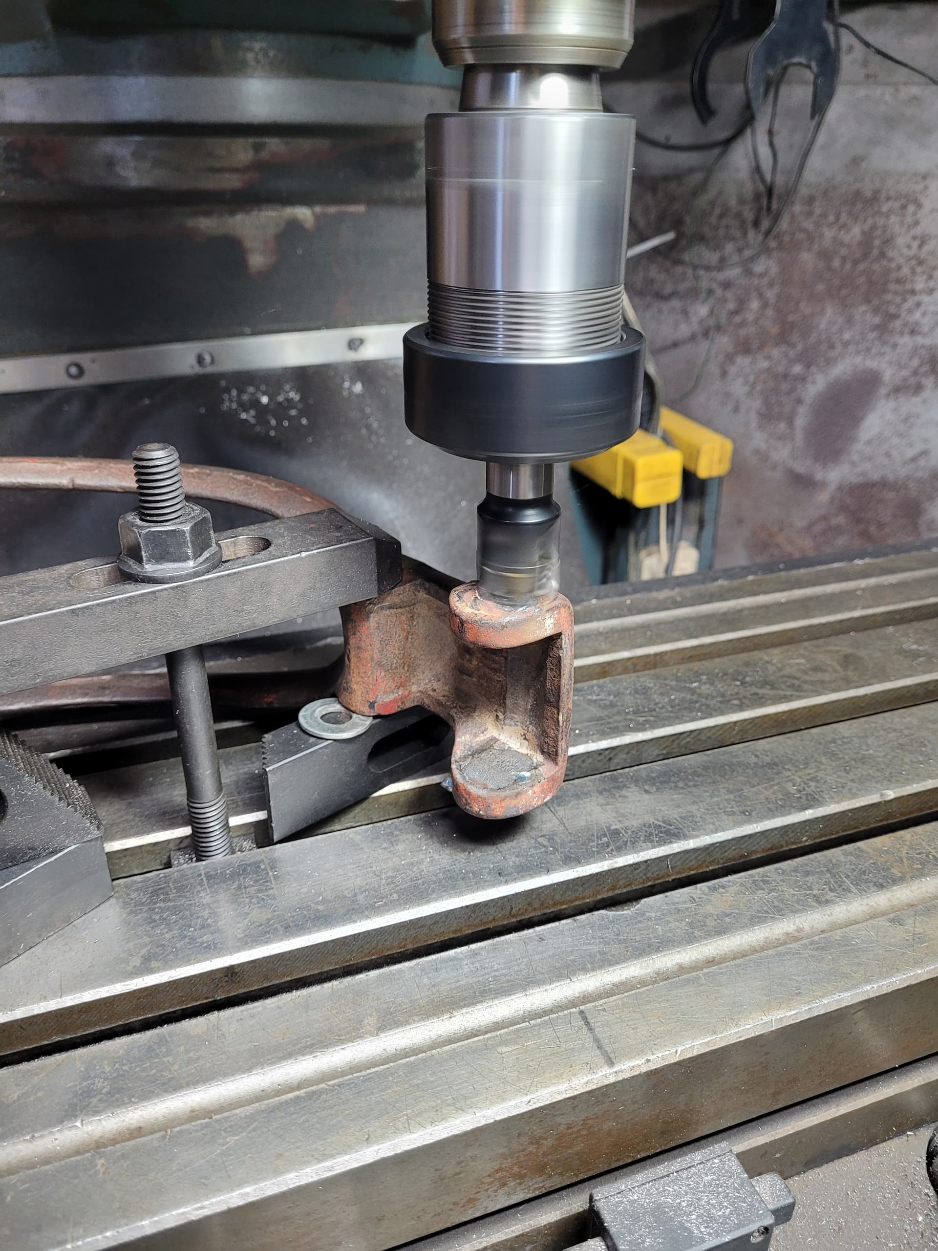
Hello all. Here’s the first arm set up in the milling machine to clean up the weld on the outside so the there is a flat surface to mark with the jig. 2nd picture is th end mill removing the excess material. 3rd is after drilling for the pin and lastly the finished arm. Fits well. 3 more to go.
Hello all. All arms are now machined for pins. Next step was to make sure the pin rotated in the perch and not the arm. Drilled and tapped the ears on the arm for a 6-32 set screw and machine a corresponding flat spot on the pin. A little blue “not come loose juice” on the set screws and all will be right in the T ing world.
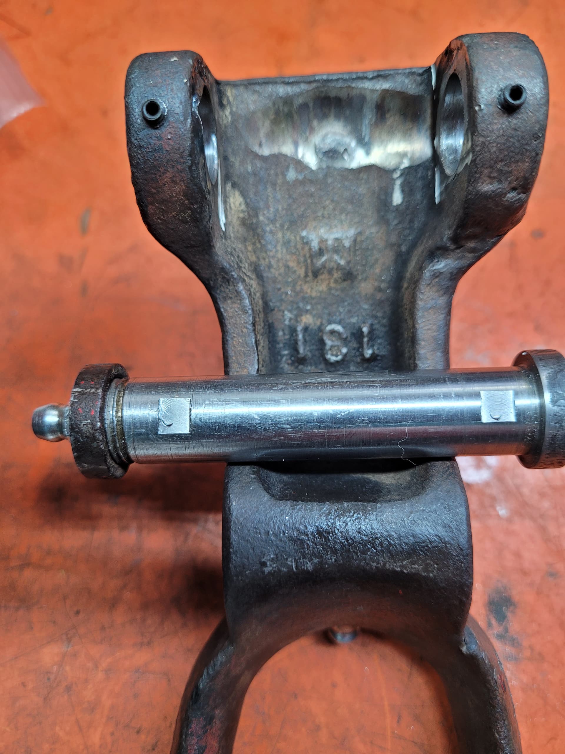
Next was to ensure lubrication for the pin on the shackle that goes in the shock arm, as there is no provision for this originally. Tried drill and tap the shackle pin. I knew they would be hard, but didn’t anticipate to the degree that they were. Being ever so careful, but a broken tap put the kibosh to that idea. So I went with drilling and tapping for a grease zerk in between the arms and a small hole in to the pin area.
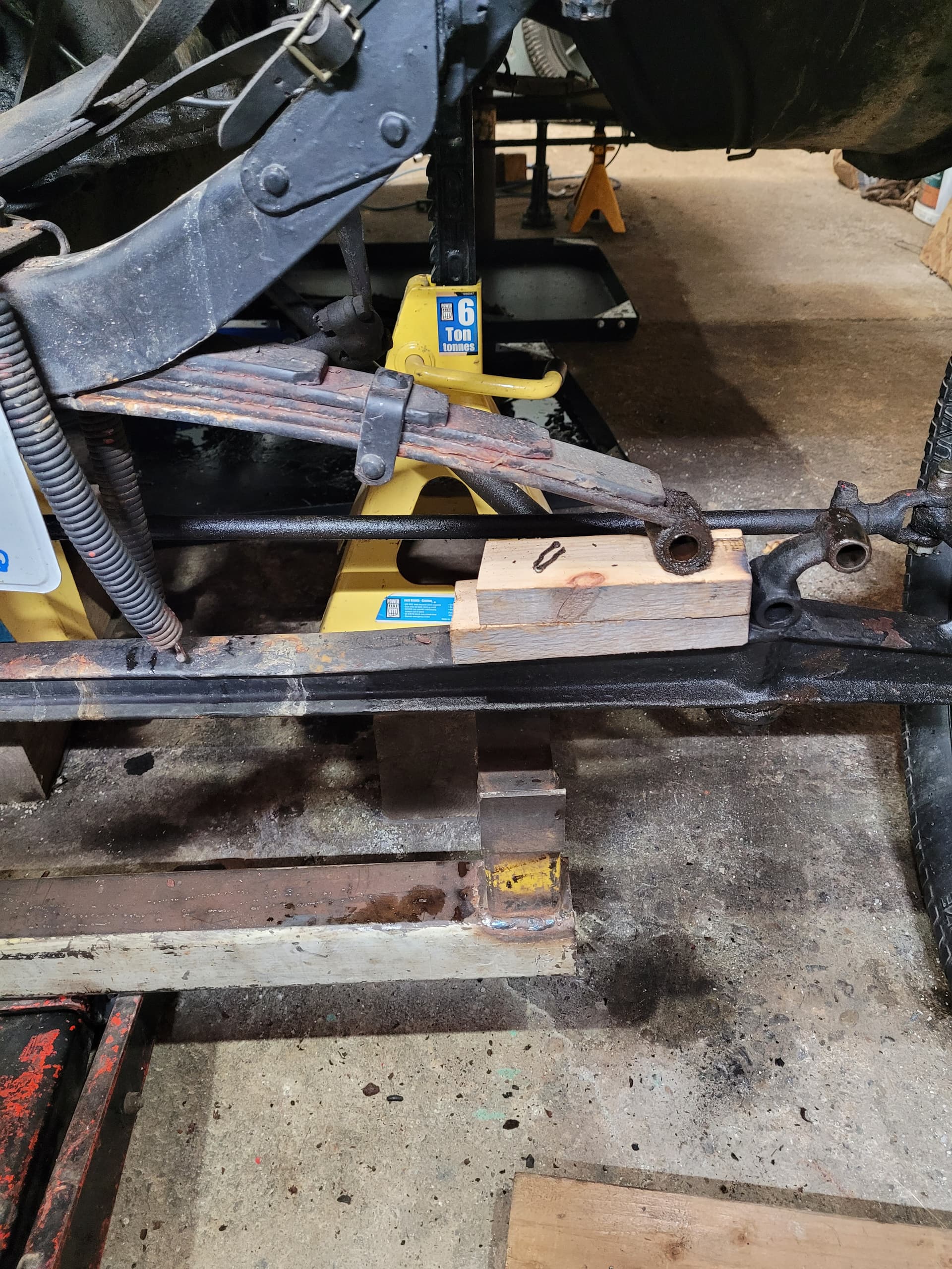
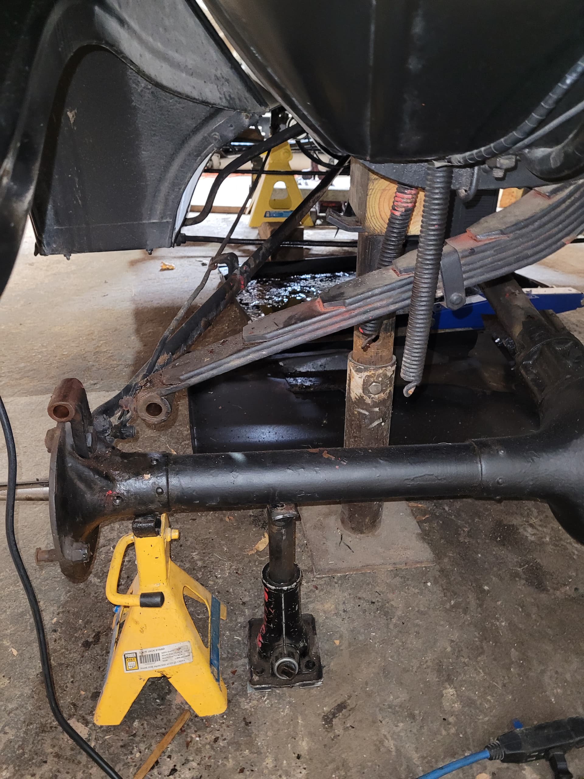
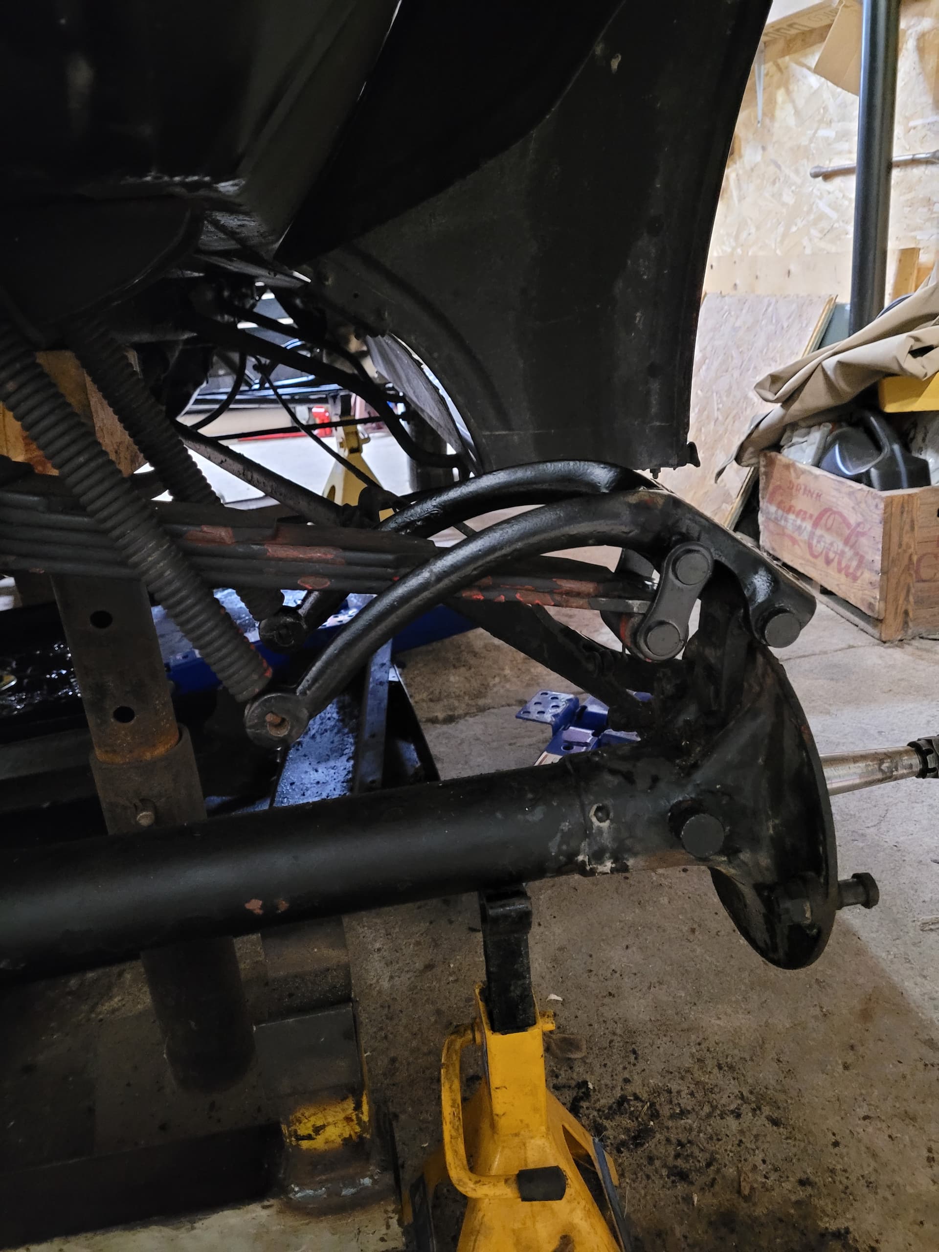
Suspension back together. Here’s a shot of one side of front and back.
On to re-lining the rear brakes.
1 Like
Well, re-lining the brakes has got to go on the back burner. Made the erroneous error of assuming that the shoes are the same. To a degree they are, but way back then, they just drilled holes for the rivets. Made the mistake of using one shoe to drill holes in the linings and they don’t fit the other shoes, and I had already countersunk for the rivet head. ![]() New linings are on order so on to doing exhaust as it has some issues.
New linings are on order so on to doing exhaust as it has some issues.
Hello all. Well, new exhaust pipe, packing nut, and rebuilt single bolt muffler installed, along with new brake linings. Just waiting for the rad. It will soon be nice weather to be out “T-ing” around.
1 Like
Hello all. Have the rad, started car and didn’t remember it being that noisy last year. The ear told me that it sounded like gears. Removed oil filler cap and there wasn’t much oil on the cam shaft/ generator gears, and I could see that the camshaft gear was looking rather worn. Yeah, we’ve all been there with a plugged tube. Pulled the engine and when I got to the tube, it had some silicone partially blocking the cup at the flywheel, and it had a dent in it about 1/2 way to the front. Well, someone before me re did the con rod babbit, and I’m cursing them as to why they would leave the tube like that. But it gets better. The reverse drum was cracked and missing a piece and a web broken. The mag coil, even though it ran on mag, had a couple of loose coils, rubbing the magnets. Glad they didn’t get caught. I now have parts and in the process of reassembly. Fortunately the gears complained. It could have been worse.
Hello all. The 19 is on it’s way back together. New mag coils, used timing gears that appear to have very little mileage. Fabricated a new oil catch at the flywheel with a considerably larger cup, and added an external oil line on the drivers side. The engine is on the stand with pan and front cover installed waiting for the modern gasket to cure. Then flip it over and install the hogs head and other things. Looking forward to going for a rip!
Hello all. Been out for a rip. Mostly okay. The usual minor hiccups. Some oil weeping from the pan gasket. Going to drive for now and see if oil consumption is excessive. It may have to come out and a reseal done. Rather frustrating, but not a deal breaker. What have you all done for front crank seals. I put hard felt in and put some grease on it for start-up, but it’s wet. Suggestions and thoughts please. Thank you!
Hello all. Looking for some insight for my 19. New mag coils and rebuilt ignition coils. Out for a drive and it died. Runs fine on battery. In checking, there was only 8 volts coming from the mag. Should be enough to run, but it won’t. Thought the mag post could be an issue and made an adapter so i could screw in a 26 post. At running rpm’s, 20 volts, but engine would miss. Removed coil box and rewired with new wire. Started car and had 20 volts, car ran nice for about 10-15 seconds, then started misfiring badly, and now my mag voltage is 4.5. Could my magnets have gone bad? Would an in car flash be a consideration? Thoughts please!
Edit: Went back to original post, but used a flat bottom spring instead of the original with a point. Saw the voltage at 4 then jump to almost 20. Flipped switch to mag, voltage dropped back to 4, flipped to battery to save from stalling and within a few seconds it was back up to 20, repeated, same result. Stopped switching and voltage would jump back and forth. All measured at the post. Car has been running great for about a month.![]()
Hello all. Think I have figured out some of the issues with the mag. .027 inch end play. Good grief. Hope there isn’t any damage to the new mag coils. Will have the engine out tomorrow and will determine course of action. Con rod bearings have been done by someone else, so I’ll likely get mains done so that the thrust can be brought back in to spec. Then recharge magnets and set it all up and try again. Going to look at rings too as #3 has low compression, and so on. Another rabbit hole is being entered. ![]()