Poormans Rajo, with Hansen-French adapter

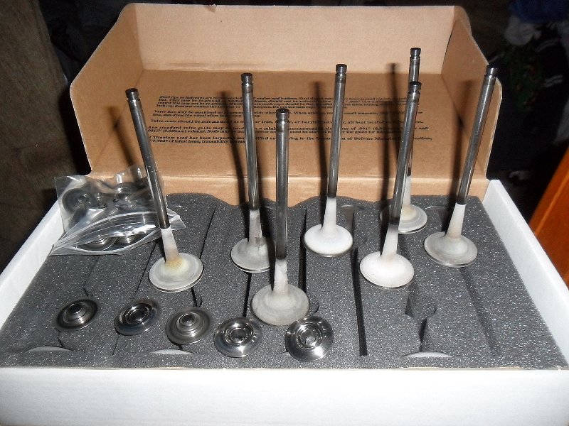
I recently purchased a absolutely beautiful machined adapter plate to put a '28 Chevy head onto a Model T block. I wanted to show you all what I have, what I think, and what may be entailed in doing this swap.

This will be a long drawn out thread, so don’t expect this done in a week. I also will be doing mock-up, not necessarily a running engine, at least at this point.

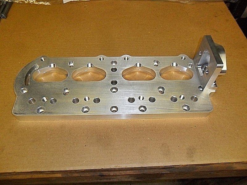
First off, the plate and water adapter are really TOO good for a Model T. Gene French started this project design and decided Scott Hansen needed something to do, so he handed the project to him to finish it and bring it to fruition. Scott has a very large machine shop. This is the kind of quality I would expect for a pure breed race engine part. Scott informed me it took 28 different tools in his machine shop to make the plate, these are all CNC’d.

Scott did supply me with hardware, and not cheap stuff either. These are high grade socket head bolts (allen head as some call them). Now the socket head hardware may not be for everyone, but except for the outer row of adapter to block bolts on the cam side, and the water outlet bolts, the rest are completely hidden. The ones in the adapter plate are all countersunk also. I suppose if you painted everything black, you could hide alot, essentially tricking the eye.


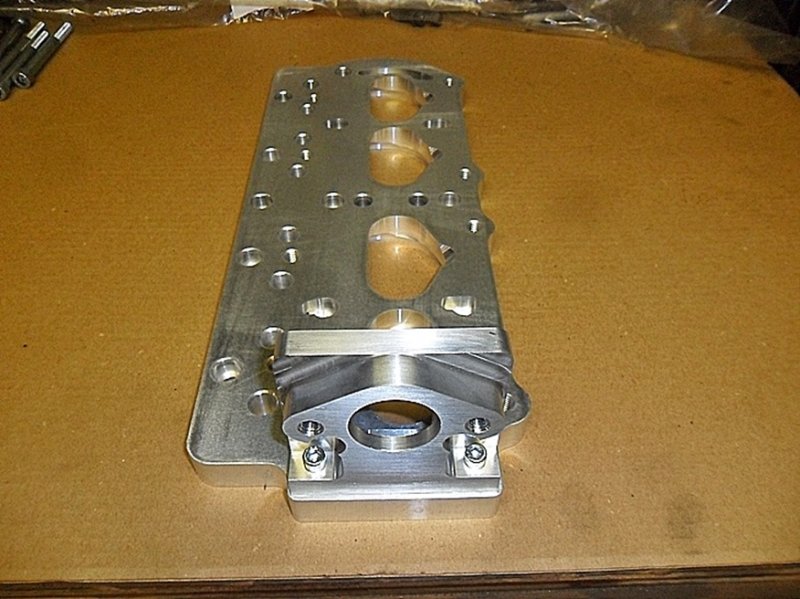
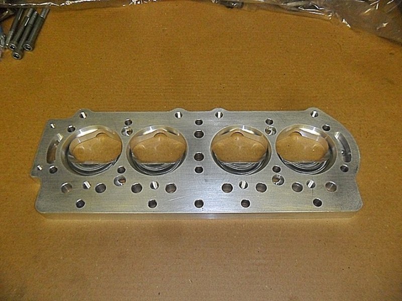
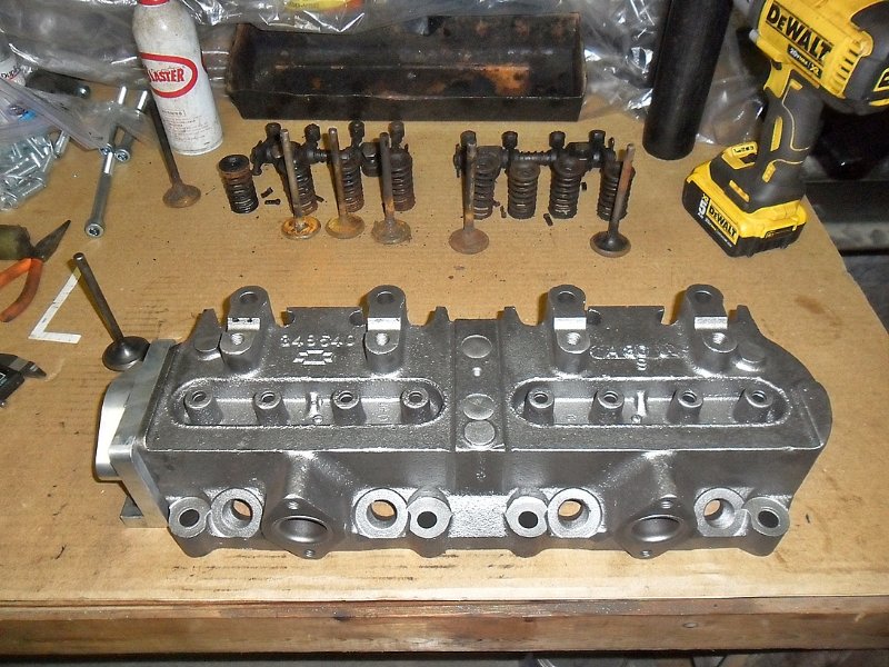
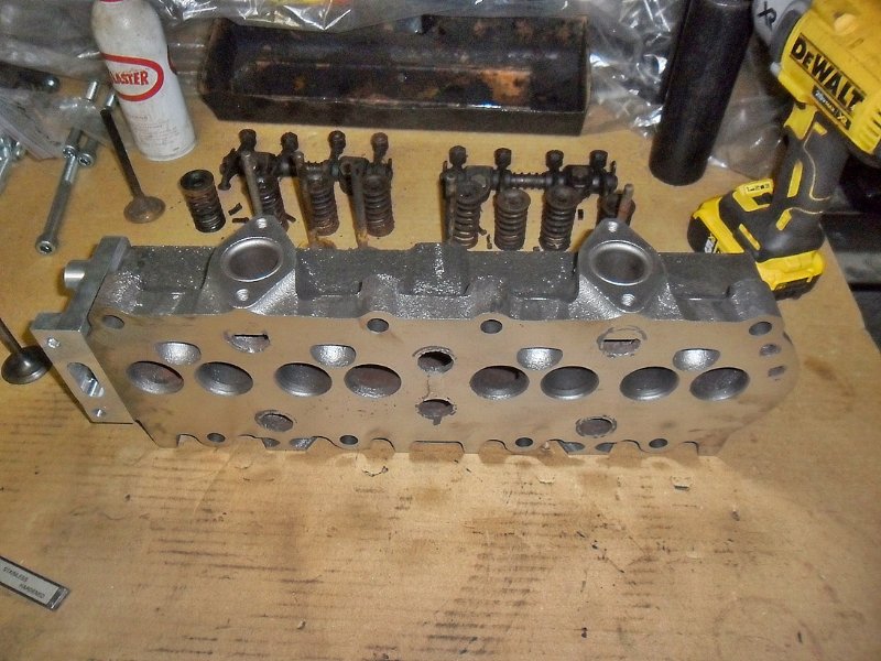
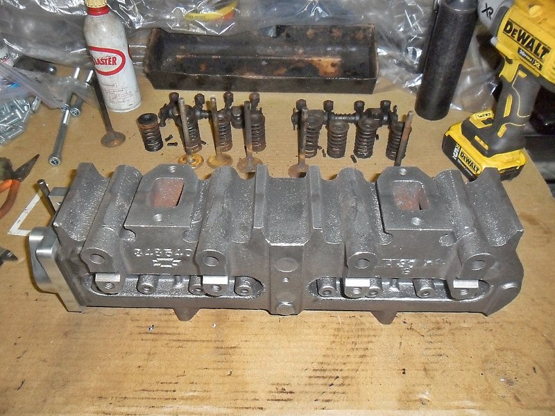
Setting the plate on the head, the first thing I noticed was how tight the chamber was around the valves. This may have to be opened up for a little more room in my opinion, which would also help to unshroud the valves a little–which is better for air flow. The fit otherwise to the bottom of the head is good, and the water outlet has a little play to fit a head if it is shaved slightly. The advantage of this water adapter over the Jern Thunderbolt kit is that the outlet does not need to be machined with the head, and it bolts to the plate offering a better sealing capability.


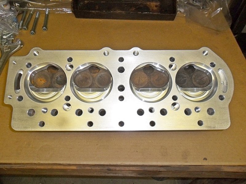
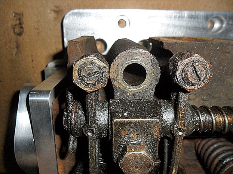
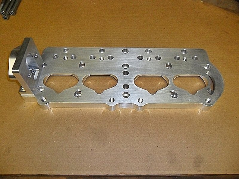
The first issue if you will (I don’t personally believe you can do this without any issues–after all, think about what is taking place), is that the two end pushrod holes are partially covered by the head. This was unexpected, but but I can see why it is. Before I purchased the plate, I had asked Gene about pushrod alignment. When Gene had answered about this to me in a previous post about the issue, he said he had used the spindly 1/4" chevy pushrods shortened, and bent the rocker arm for better alignment. I don’t know and will have to check about if he also experienced interference in the plate and head in this area. I’m thinking a little grinding here may be in order, but would like to find out what has been done first By Gene or someone else.

What is the point of supplying the kit with socket head bolts? Why
not supply period appropriate hex head bolts of similar strength ?

Is there a proven performance advantage to doing something like
this ? If so, what might one expect over say, a Z-head ?

Thanks for any intel.

It is some amazing machine work. Can’t wait to see how it turns out.

Raoul,

You absolutely need either a socket head screw or a reduced head size screw (such as those by ARP Fasteners), as they have to be below the surface on the adapter to block portion. How the water outlet attached to the head also requires a fastener of the same style (although it will be mostly hidden by the T water outlet), and I am fairly sure your not going to get a standard headed screw to fit in the water outlet to head adapter plate holes either. This is a compromise for authenticity, and definitely function over form.

On the outer exposed row of bolts, you could probably find period hardware that would fit, although then you’d have to fill the countersink in the plate so the bolt head sat on top of the plate. Attaching the T water outlet to the water adapter you can also use stock /period hardware there too.

Performance is definitely increased, some say it near doubles the horsepower. An overhead valve arrangement will always have the the POTENTIAL to make more power vs. an in block valve arrangement. I say that statement with a little reservation, but apples to apples, airflow “should” always be increased on an overhead valve arrangement. And an engine is just a giant air pump. The more air you can get in and out of it, the more performance you will get. That is simple math.

So why do this over say a real Rajo or Frontenac. Same reasons it was done way back when, COST. If you manage to find a RAJO or Fronty head complete with all the valve train and manifolds, for under $1500 in today’s world, you scored real good. Truth be told, if you find good used parts from a seller, you will probably be spending $2000-4000 for a “real” setup with a reproduction falling somewhere between that. And then those originals, still often need machine work done to bring them back to life. I still feel there are some stuck in garages or barns, and they could probably be purchased alot cheaper if you can find them and hunt them down, and if the seller doesn’t know what they really have.

I feel I can do this whole setup for around $1500-1600. I currently am at the $800 mark, with a machine shop bill on the way. I tend to go overboard though as I build musclecar engines as a hobby and used to drag race. So you will probably see alot more modern “racier” stuff stuck to this thing that may or may not be necessary and can be taken out of the cost for an average builder or someone that wants something more period. An example, I am searching for some “race style” valves for the head–something that is designed and shaped to promote air flow and is lightweight.

I hope that answers your questions, and also sheds more light on my intentions. There are many ways to go here, the choice is yours.

I spoke with Gene Frence last night, he said my head appears to have more casting material where the end pushrods go than his that he used for a mock up. He did however still clearanced his head to clear the pushrods. That part of the head is purely superficial and can be cut off in reality. So I am unsure in the direction I want to go here.

On thing becomes quite apparent quickly though, there is pushrod / rocker alignment issues that need to be dealt with. This absolutely explains why the late Neal Jern (Jern Thunderbolt kit) used a 2 piece pushrod to deal with these issues. I may also go with two piece pushrods.

So, these socket head bolts sit UNDER the installed head, and most
cannot be seen ? The bolts used to secure the head to the engine will
be what is largely seen, like normal ?

I love this idea, but always angle for how to make it look as if the
work was done in 1925. To this T guy, the period look and charm over-
rules all other considerations. Gotta make it look old !

What head specifically, is needed for this application … particular
engine or years ???

The bolts on the outer cam side of the motor can be seen on the adapter after assembly. As I said, you can fill the holes and use other period bolts.

The outside row of bolts on the cylinder head can also be seen–again, you can run period bolts (BUT!, you can not run original Chevrolet bolts as they are 1/2" x 12, vs. the modern 1/2" x 13 thread)

The ones in the rocker shaft area are hidden under a valve cover. There is no pressure oiling to the top of the head, the stock setup relies on a oil soaked felt sitting on the rockers for lubrication, there are ports / holes in the stock valve cover to oil through to the felt. It is conceivable that you could run this as a open valve setup, it would certainly garner some more attention that way, but keeping up the oiling either way is important.

I get the fact you want it period. I try to keep my T pickup relative to that, but it too is modified as it has a cut off touring car for the body (done way back when–not by me). You could easily make this all period looking with a little thought. Most guy (like me) would want to show it off. And as a performance guy, I am always looking for improvement.

This whole setup is designed to use a '28 Chevrolet (two port) cylinder head. I Believe that a '27 single port head still can be used also as it is the same head gasket, but with the single intake port, you lose some airflow.

I will also say that I have uncovered different readings that people say this increases horsepower but at a lower RPM, vs some of the RAJO or Fronty heads that make the horsepower at a higher RPM. To me, considering you are riding on poured babbit bearings, the lower RPM sure seems alot safer, but there are so many things that can change that, the head flow is just one of them.

I enjoy reading about your build, and especially the pictures. TThe more details the better to help the next guy.

Tom, Thank You!

That is also precisely why I am doing it–to help the next guy. I searched in great length on this project, there are many ways to reach the end goal, but no one ever showed how exactly they did it. I enjoy doing “build threads”, done it for years on other forums with much newer stuff. I really hope others get enjoyment out of it like I do, because it is a lot of work to type these up with detailed good quality pictures.

Update, I just received my head back from my machinist, will post up pics later.

I like keeping tally of what I spend, it is something I use to keep me in check (even though I don’t ever maintain my budget).

So the tally so far:
$240---------Used head with valvetrain and manifolds and shipping
$560-------- CNC’d head adapter plate with water outlet adapter and hardware
$86.40------Bake and blast cylinder head and machine deck to flat

$886.40

Safe to say you could conceivably bolt this thing together with a couple of head gaskets and be at the $1000 mark. That’s not what I do, so I will continue on.

Promised pics of the cleaned head.

We had to mill alot more off than we intended to to make it flat. Somewhere around .030"-.035" was removed. This was because there was a crack in the center two water / steam holes and someone tried to weld it to seal it. When you do something like that you create a low spot from the heat. Plus we are assuming by the look of the repair, that it was mig welded. That is not a stable repair in general to cast iron if especially if regular steel wire was used.

After machining the weld still seems stable, albeit still ugly looking. All the pits you see can be filled with a little high temp silicone or if your particularly anal, JB Weld (best to do that before milling the deck surface though). Because we had to mill so much off to get a flat surface for the head gasket, we bolted the water outlet on for the final pass to make it all even. If your head is in good shape, as I mentioned before, you should not have to mill the water outlet with the head (such as the case was with the Jern Thunderbolt conversion.)

The other surprise bonus that turned up from milling the deck alot was I am not now stuck using a odd valve size. The excessive milling removed alot of the valve seat area. Normally you’d want to use a larger valve to increase air flow. The head gasket in this case is the limiting factor, and add to the fact the adapter plate shrouds the valve pretty good–not good for air flow. So in this case, I am going to downsize the valve size, use a smaller stem to also help save weight, Both which “should” help air flow in this case. The valve guides are completely worn out, so I will have guides pressed into the head to accommodate the valve stem size used. I should be able to have a bronze guide installed for better friction / wear properties. This particular head has been run hard and dry.


I am eager to see this thing all put together. As many know, I
want to build a TT to attempt a world land speed record. Currently,
top speed is well above 40 and some creative head application
might be just the ticket to getting the old dog up on two wheels
in the corners. But having some extra-funky looking Rube Goldberg
whirring parts under the hood would be an even bigger incentive
to taking on such a project. Hehehehe ! :stuck_out_tongue_winking_eye:

I know it seems like I am moving fast on this, but it won’t always move nearly this fast. I just have way to much on my plate for other projects and house upkeep for that.

Right now I am stalled trying to determine which valve/retainer/lock/spring combination I can make work. I also need to disassemble the rockers and shafts to clean them. I know I have some worn rockers in the shaft area, I am not sure what to do with them at the moment, hopefully the shafts are ok.

A TT can move fast, no doubt one of the key things you will need is a high speed gear set. And then in my opinion an overdrive auxiliary transmission too. The other thing I often hear about them going fast is driveshaft “whip” (vibration) caused by the length of the shaft. I believe if someone could bush a driveshaft tube midway it would cure that issue, but then it would have to be line honed. Again, all my opinion.

Superior engine performance can be had with a Rajo or Fronty head. They truly have better flow in them. The Chevy head flows good, just not as good as those. And engine power is all about air flow in and out of the engine.

Super cool Chad! I hope I get to see it in person at some point. My project is nearly it’s first run. What are your plans for the bottom end of this engine and what car will it go into? Do you think you may be running it by next Sep? If so perhaps a good test will be my clubs banquet and hill climb in Plainfield ma. Thats my goal to have my car running for that event.

David, I have no immediate plans as for a complete engine. When I get this all figured out, I told my buddy Ron its liable to end up on the doodlebug for testing. I am not sure if I want to put it on my '25 cut-off pickup or not. I am currently collecting parts to build a new engine for the cut off truck—that one has a Scat crank, aluminum pistons, and will probably get a Prus head. That would be a great comparison to do. And it could and probably will happen. Ultimately, I want to build a Speedster pickup, and am collecting parts for that too, and that is where this will hopefully end up in the end.

Really, all I want to do at this point is get all the how’s and why’s figured out. Once I get that all done, putting it on any engine shouldn’t be an issue, short of drilling two center coolant holes in the deck of the block and a set of head gaskets. There are twenty ways to do this, like I usually do, I am going to find the hardest way, LOL.

You could always stop on by too, I know it’s a little hike for you, but really not that bad. I want to see that beautiful speedster in person my self at some point.

I got the chassis completely done, in primer. I am putting engine back together. I got the output aligned to .0025 so I’m good there. I put the new drums and news gear on and got everything torqued and safety wired. This weekend will be putting clutch together and lining bands. I will still need to go through the hogs head and install new shafts and notches. So really it getting close to its first run! We will have to see how a balanced flathead with hc pistons does against an overhead :smiley:

The TT has been rebuilt with a micro-tolerance balance, Z-Head, Scat Crank,
aluminum pistons, C-race cam, and I current run a straight-thru NH because I
have been a slacker and not gone through my OF like I need to. The Ruckstell
was rebuilt with the express gears. In the process, I picked up a new radiator
and lost the fan and water pump. It has run very well all summer. I use a local
hill as my testing grounds and where Ford low was mandatory before the rebuild,
I can now cruise it in high and actually have to back off on a mid-hill flat spot
with a curve, or I get the thing up on two wheels. Top recorded speed has been
48mph on flat ground, but she’s really “humming” !

The scheduled winter work are to rebuild and install a Lincoln 3-speed aux.
transmission, do the OF and get it on, as well as little detail stuff like a new
rear wiring harness, adding some period turn signals and stop light and perhaps
push forward on my Rube Goldberg air compressor system for a steam whistle.
Oh yeah, … and send the wheels off to Stutzman for a rebuild. Oh yeah, and
finally get safety glass installed. Probably 3 more things I am forgetting …

Model T’s are an endless case of “Oh yeah’s” …

I ordered up some valves, retainers and retainer locks today. Going to try something different here. I ordered some used titanium valves from a Nascar Cup car. These are small stem light weight valves. Only issue is they are a little longer than I need. I can cut the length and reface the stem easy enough on my valve machine, cutting a new groove for the valve lock is going to take some experimentation, so we’ll see where this goes.

I could never afford these exotic valvetrain parts new, but for the limited mileage (although hard miles) these engines run, and the comparatively light valve spring pressures we’ll be using here, these should work fine. The plan is to have my machinist put in a set of bronze guides and even though I can cut the seats myself with my old school seat grinder, I’ll just have him do it as he will be able to repeat all 8 seats the same, thus making setting up all the valve heights much easier as they can be all the same. And he can also do a multi angle cut on the seats to improve air flow.

I’m still looking into valve springs. I believe I have found something that will work, I just need to do more verification on that. These springs would require reducing the diameter of the cast in valve guide, but that’s not an uncommon modification in the performance world.

Minor update. These are the valves I am hoping to use. These are 7mm stem, 1.630", coated heads, titanium valves and titanium spring retainers. Super light weight, and way overboard for this application. Courtesy of an Ex Chevy Nascar engine. The valves need to be shortened and have the lock groove recut for these to work. Neither one of those mods should be a big deal. The bigger deal (not really though) is I have to shorten the guides in the bowl of the port, to accommodate these, but that will also promote airflow.

Phillip Reinhardt is doing something similar, I am linking his pictures here:

https://www.facebook.com/groups/Fordmodelt/permalink/10159432375485548/

Here’s the video of Phillip’s engine running:
https://www.facebook.com/philip.reinhardt.58/videos/10211339612628249/

Sunday I am going to Connecticut to see a conversion first hand that was done and running. He has a different adapter plate, but obviously all this is roughly the same idea no matter who does it.

Hope to comeback with lots of pictures and some better ideas. He said it runs great, does not over heat (no water pump either), and is pretty darn fast. He noted it feels a little under carbureted, but I will have to get more info on what’s there currently.