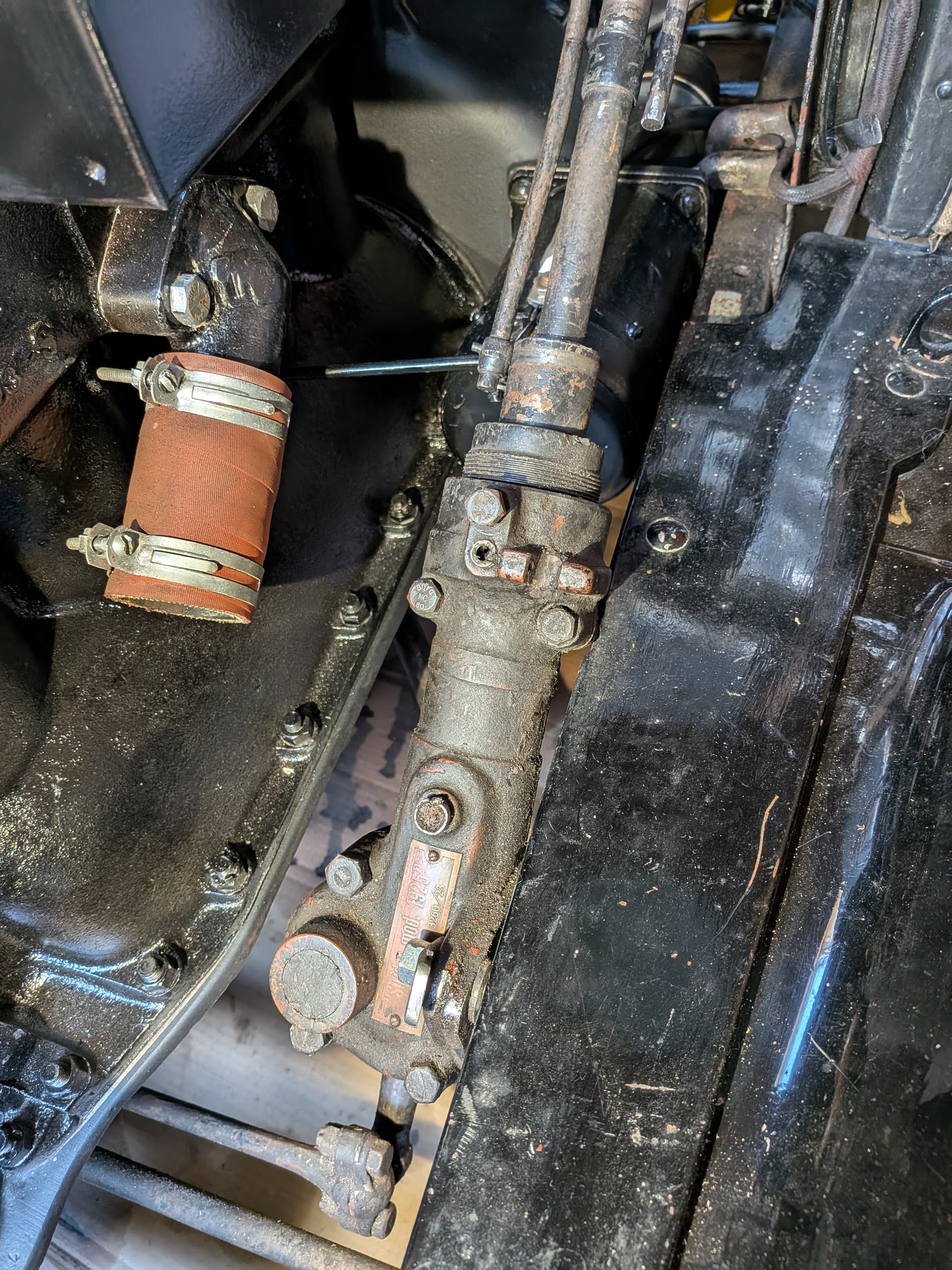
The problem is that this device interferes with the spark rod, which is supposed to run parallel down to the bottom of the steering shaft. Because of the bulky shape of the add-on, that’s no longer possible.
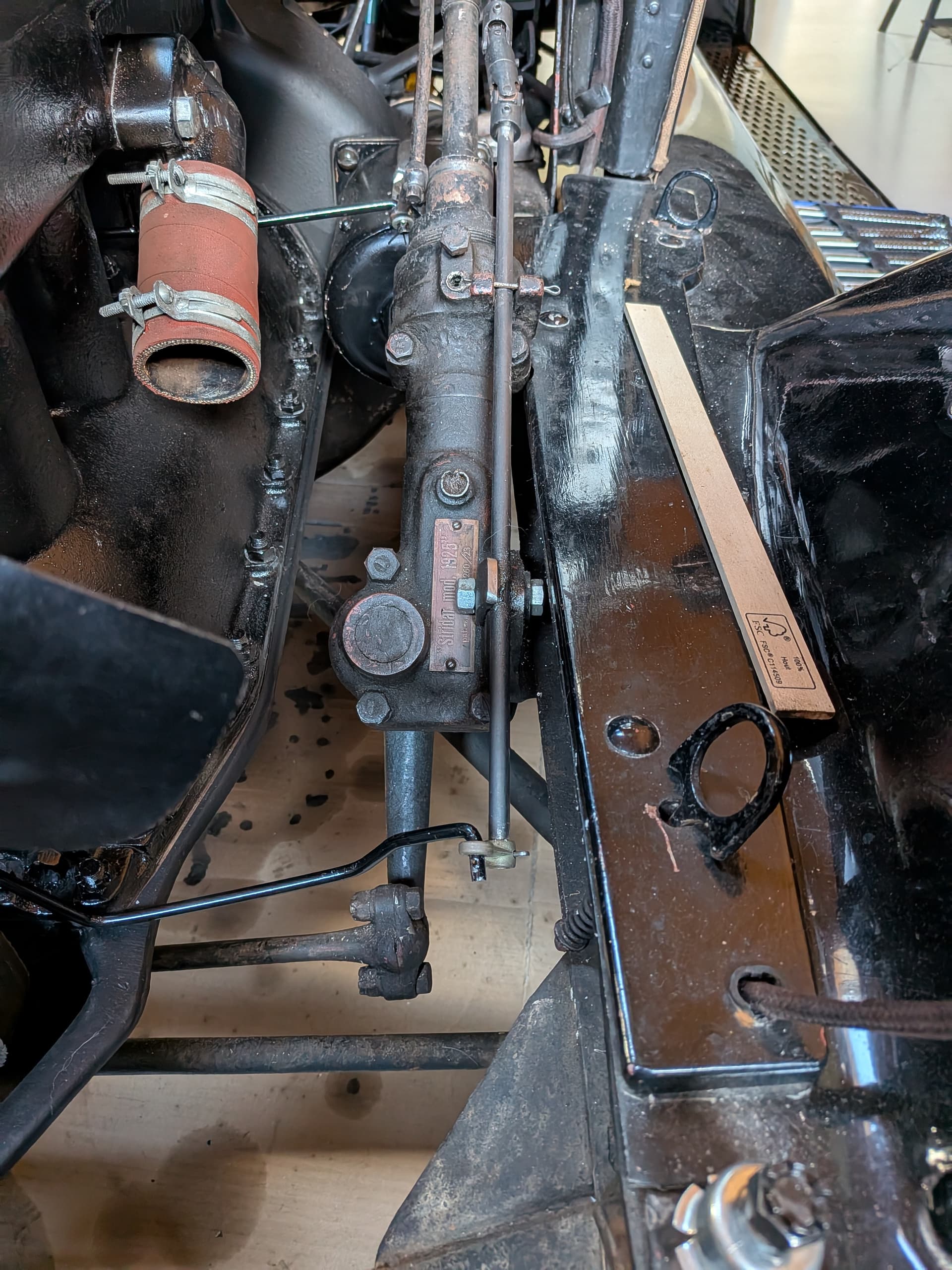
The previous owner worked around it by bending the rod, but that creates an awkward, non-linear swing at the end, directly affecting the spark timing.
I tried an alternative solution by adding two cardan joints. Unfortunately, I’m not happy with that either: it still looks odd, and the connection feels too loose. I can move the spark lever nearly halfway before it actually moves the commutator.
Of course not familiar with that special geared steering box, obv. Swedish made from the link. Viewing the casting of the box, appears the upper guide for the spark rod is there, where you have the cotter pin located, and the lower bracket with the bolt and clamp to provide alignment of the spark rod. Those u-joints may be the reason of the excess movements, so the best fix would be to use a straight spark rod, as in original.
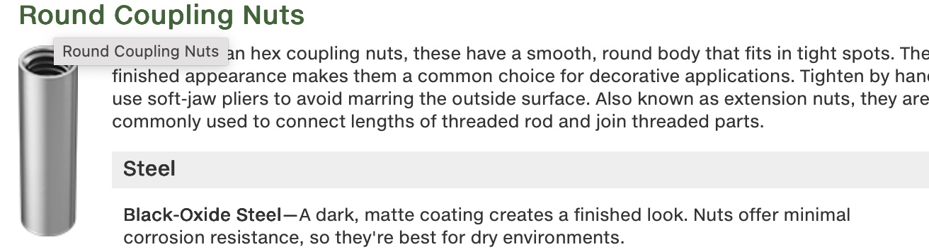
Might be able to use an inline coupler, a smooth coupling nut could work, by threading the ends of the rods, both on the upper remains of the original rod, and then extend a straight rod from that coupler nut. Image of the coupler below, that pic was from website of McMaster-Carr, a USA supplier of many mechanical items.
Replacing the upper cut off rod for an original long one is an elaborate task as the upper gear cluster under the steering wheel has to be removed by driving out the rivets at the column, to completely disassemble the steering column.
If using the pieces you have it, might be able to get back to a solid rod, by that inline connector, to eliminate the excess wiggles. Then the timer or commutator rod might have to be adjusted by bending at the curve near the timer case, to reset for the correct timing.
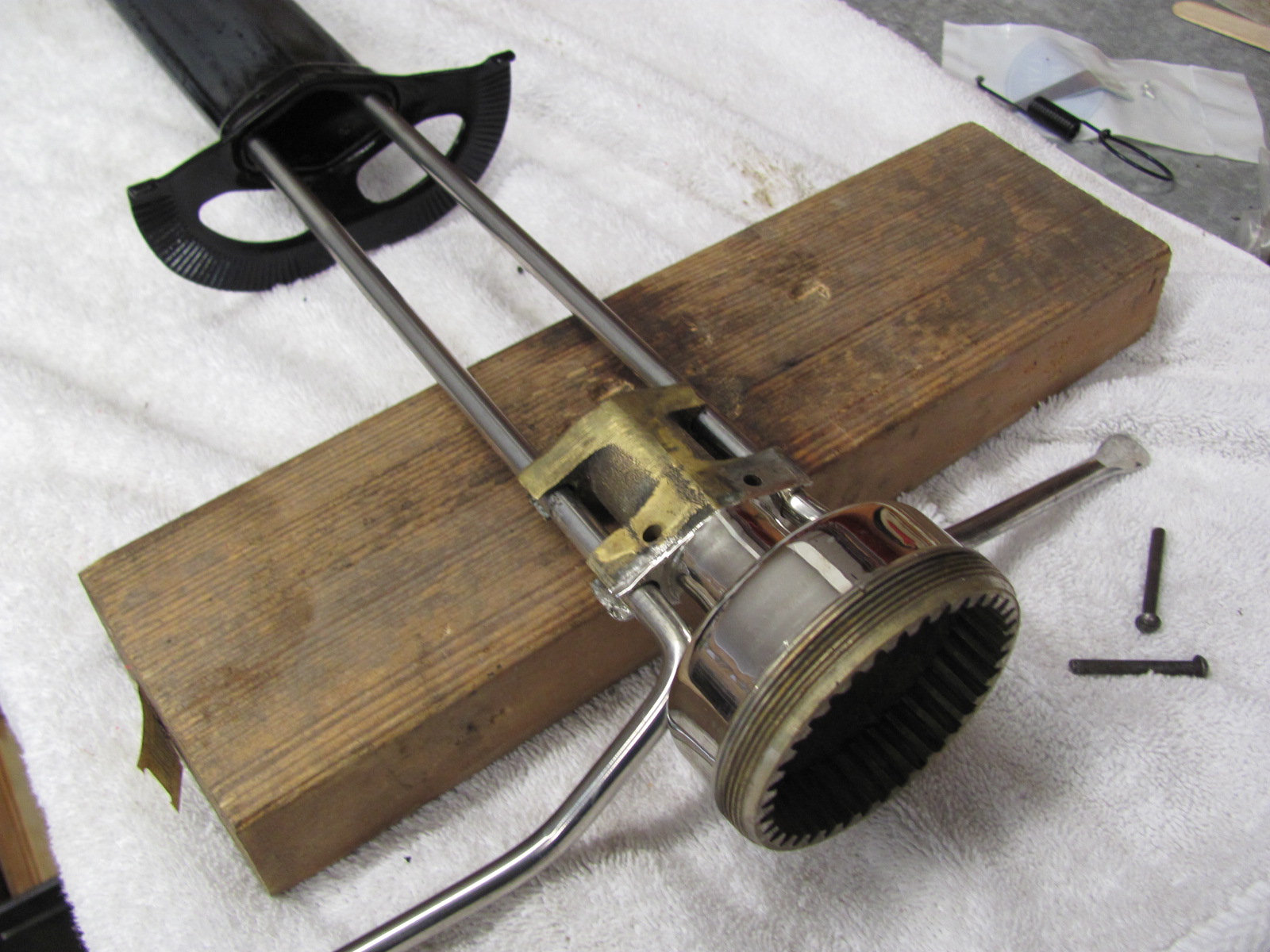
How the cluster is removed from the column to replace the spark lever rod, it is held with small fingers of the brass case, bending very slightly, to just allow the rod to escape, as the brass can fracture, sometimes annealing the brass fingers can prevent total fracture.
Initially, I also thought the rod should pass through what you call the upper guide. However, that opening doesn’t line up with the spark rod coming from the dash, neither horizontally nor vertically. In addition, the opening is somewhat V-shaped, which causes the spark rod to “dangle” when rotating the spark lever. This seems to be part of the reason why in this setup, the commutator doesn’t even begin to move during the first half of the spark lever’s travel.
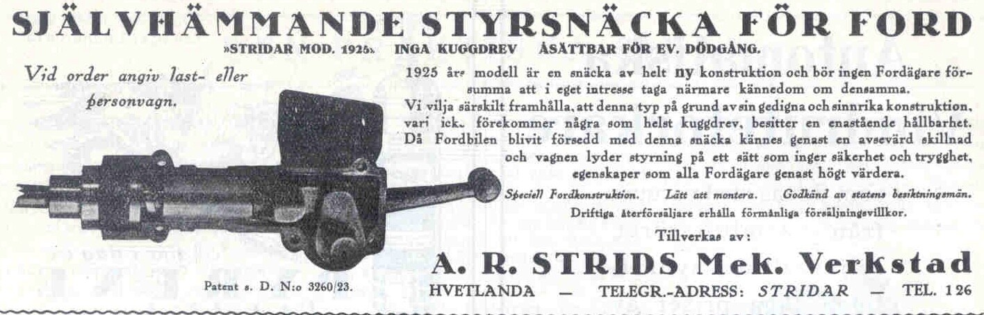
I’m really curious how the manufacturer of this steering box originally intended the spark rod to be routed.
I’d prefer not to remove the steering column to replace the spark rod with a new one, so I plan to either weld something to the existing rod or use a coupler, as you suggested.
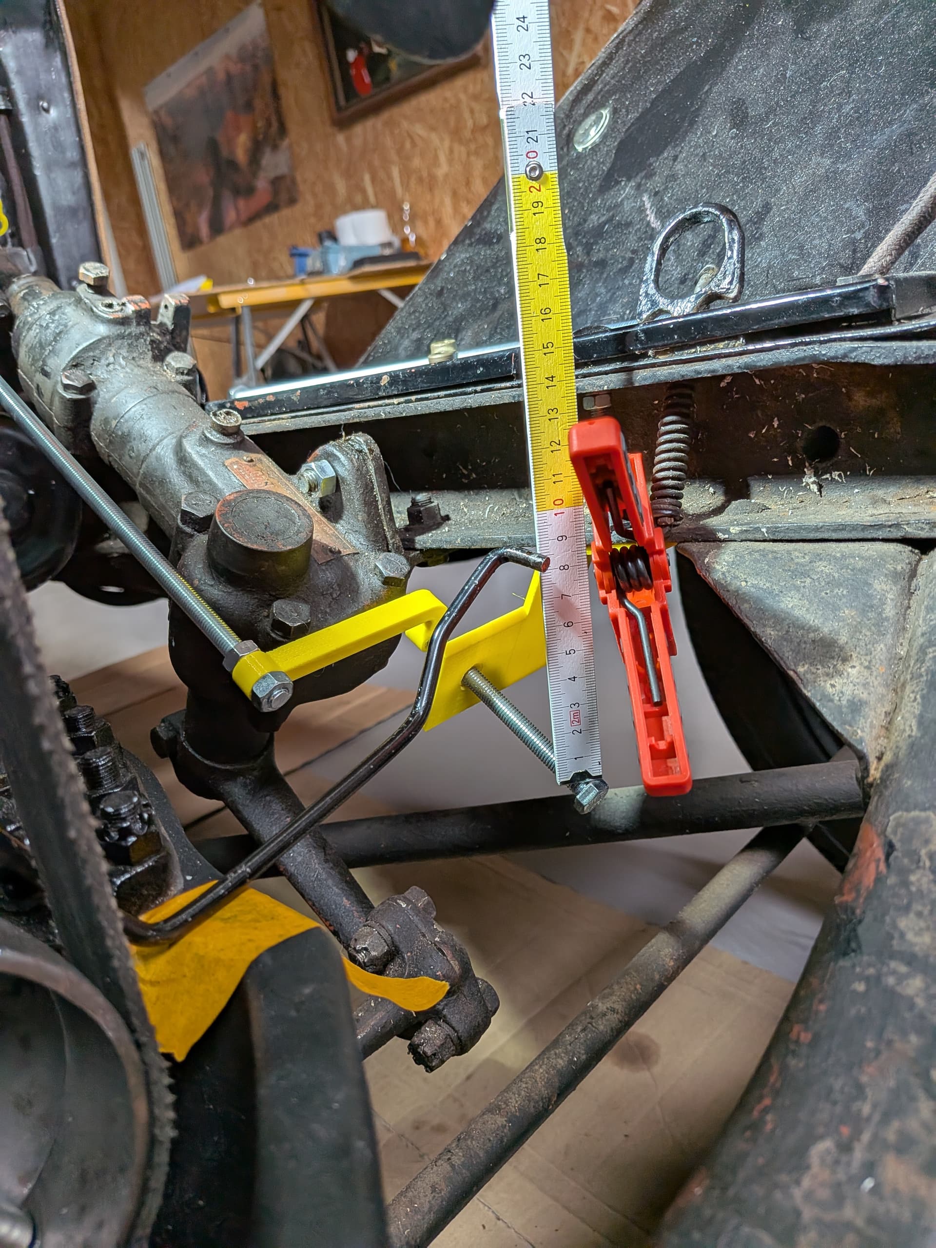
In the meantime, I’ve been experimenting to see if I can get the spark rod movement to clear the steering box. I’ve 3D-printed some temporary plastic parts, (so definitely nothing final!) but this setup at least lets me reach the position I think I’m supposed to achieve. The current solution looks even more hideous than what I had before, but at least the looseness is gone.
That said, I’m still not entirely sure what I’m aiming for. I have a few questions:
Should it be possible to pull the spark lever all the way down (with each step causing the commutator to rotate a bit), until it reaches the last notch on the back plate?
I have the original Ford roller and commutator, so for now I can probably use the “2.5-inch method” (when the lever is fully up) mentioned in several other posts and articles. However, since I don’t have a reference to the original setup, I’m unsure about the correct commutator position when the lever is fully down. Is there a factory-specified distance or setting for this as well?
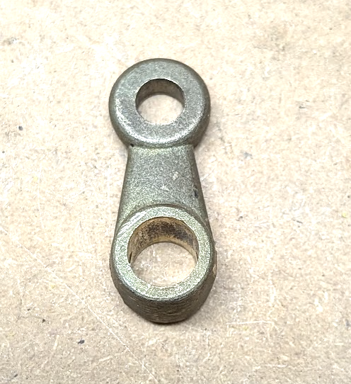
For connecting the spark rod to the commutator pull rod I have ordered this deflection lever. Is there any way of describing the exact position and orientation of this part?
I’ve also ordered the original commutator pull rod (the one that runs underneath the radiator pipe). But when I attach it to the commutator, the other end sits well above where my spark rod currently ends. This makes me think something is still off. Am I supposed to bend that rod downward at the right end to make it fit? See image below:
Please know that I’m aware of the more accurate way to set the timer (by measuring 15 degrees past TDC). But for now, I just want to get the general setup working before fine-tuning it.